Key takeaways
- ANSI pad-mounted transformers are dead-front units with 200 A loadbreak bushings and tamper-resistant enclosures to ANSI C57.12.28.
- IEC-style pad-mounted units are more commonly live-front or use separable connectors sized to local MV switchgear practice.
- Loop-feed designs use two sets of bushings so the transformer can be switched without interrupting adjacent loads; radial-feed uses one set.
- 60 Hz cores are typically sized with slightly higher flux density margins than 50 Hz cores of the same rating to control losses and noise.
- Standard ANSI kVA sizes run 75-2500 kVA at 12.47/13.8/34.5 kV distribution classes with BIL ratings matched to system voltage.
Pad-mounted transformers built to ANSI conventions and those built to IEC conventions solve the same problem — stepping medium voltage down to utilisation voltage at ground level, outside a building — but they differ in bushing interface, enclosure philosophy, and how loop switching is handled. For a utility or EPC firm bidding into 60 Hz markets across North America, Central America, and parts of South America and Southeast Asia, understanding these differences is what keeps a specification, and a factory acceptance test, from becoming a rejection.
Dead-front vs live-front construction
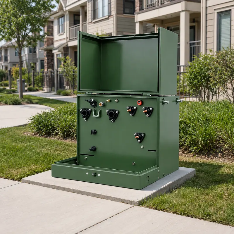
The defining feature of the ANSI pad-mounted transformer is dead-front construction: every medium-voltage connection is recessed inside a bushing well, engaged by a separable loadbreak elbow connector, so that opening the enclosure door exposes no live conductor. This is codified in ANSI C57.12.28, which also sets tamper-resistance requirements for the enclosure — penta-head bolts, interlocking doors, and enclosure strength tests against pry-bar and impact attack, because these units sit unattended on public and commercial property.
IEC practice historically favoured live-front pad-mounted or kiosk-type transformers with bushings terminated through separate ring main units or fused switch-disconnectors mounted alongside the transformer, particularly in Europe where compact substations combine LV/MV switchgear and transformer in one housing. Where IEC-influenced markets adopt dead-front pad-mounted designs — common in parts of Latin America, the Middle East, and Southeast Asia — they generally converge on the ANSI bushing-well and elbow interface because it is the dominant commercial standard for underground residential distribution (URD) equipment, rather than maintaining a separate IEC bushing geometry.
Loop-feed and radial-feed configurations
Two switching arrangements dominate the pad-mounted transformer market:
Radial-feed units have a single set of primary bushings and serve one dedicated circuit tap. They are simpler, lower cost, and suit isolated loads such as a single commercial building or a small industrial site.
Loop-feed units carry two sets of primary bushings — source and continuation — connected internally through loadbreak switching so the transformer forms part of a cable loop. If a fault or maintenance need isolates one transformer, the loop can often be re-fed from the opposite direction, improving reliability for residential subdivisions and campus feeders. Loop-feed designs typically add internal bushing-mounted switches or, on larger units, a small integral switchgear compartment, increasing footprint and cost over radial-feed of the same kVA.
The choice is largely a network-topology decision made by the utility or site designer, not a transformer performance question — but it changes tank size, bushing count, and price, so it must be fixed early in the specification.
Bushings and 200 A loadbreak elbows
ANSI-style pad-mounted transformers standardise on 200 A loadbreak elbow connectors engaging bushing wells built to IEEE 386 dimensions, for primary voltages up to 34.5 kV class. This interface allows field crews to make or break connections under load using a standard shotgun stick, without opening any enclosure to live parts — a major factor behind dead-front’s dominance in public rights-of-way.
Where higher current transfer is needed — typically on the source side of a loop, or for larger three-phase loads — 600 A bolted bushing wells are used instead. These are not loadbreak rated; switching at that current requires separate load-interrupter equipment, either integral to the pad-mount or in an adjacent ring main unit. Specifying the wrong bushing class for the expected fault-make and load-break duty is one of the more common errors in pad-mounted transformer procurement, so the specification should state both the continuous current and whether field switching under load is required at each bushing position.
Tamper-resistant enclosures: ANSI C57.12.28
Because pad-mounted transformers sit in yards, sidewalks, and parking areas accessible to the public, ANSI C57.12.28 sets minimum requirements for enclosure integrity: penetration resistance, pry-resistant door latching, and a high-voltage compartment that stays closed under a defined force. Compliance is usually demonstrated by type test rather than routine test, so a specification should ask the supplier to confirm design compliance with C57.12.28 and, where the project requires it, to provide the underlying type-test report.
Voltage classes, BIL and insulation coordination
Pad-mounted transformers for 60 Hz distribution networks are most commonly built for the 12.47/13.8 kV and 34.5 kV nominal classes, matching the two most widespread North and Latin American primary distribution voltages. Each class carries a standard basic impulse level (BIL) set by ANSI C57.12.00:
| Nominal system voltage | Typical BIL | Common application |
|---|---|---|
| 12.47/13.8 kV | 95 kV | Urban/suburban underground residential distribution |
| 25 kV class | 125 kV | Regional distribution feeders |
| 34.5 kV | 150 kV | Rural and industrial feeders, longer runs |
BIL must be coordinated with the switchgear, cable terminations, and surge arresters on the same circuit — specifying a transformer BIL in isolation, without checking the rest of the insulation coordination study, risks a mismatch that undermines lightning and switching-surge protection.
60 Hz core sizing vs 50 Hz
Core flux density in a transformer is inversely proportional to frequency for a given applied voltage and winding turns, so a core designed for 50 Hz duty, if simply relabelled for 60 Hz service without redesign, would run at a lower flux density and be over-conservative — while the reverse, running a 60 Hz-optimised core at 50 Hz, risks saturation and a sharp rise in no-load losses and noise. In practice, transformer designers set the number of turns and core cross-section specifically for the rated frequency, so a genuine dual-frequency requirement (for example, a project bidding into both a 50 Hz and a 60 Hz market) is handled as two distinct designs rather than one core rated for both. Buyers should confirm the frequency at order entry and treat a “50/60 Hz rated” nameplate claim with the same scrutiny they would give any other electrical rating.
Standard kVA sizes
ANSI pad-mounted transformers are offered in a standard kVA ladder, typically: 75, 112.5, 150, 225, 300, 500, 750, 1000, 1500, 2000, and 2500 kVA, three-phase, at the voltage classes above. Sizes above 2500 kVA are generally handled as substation-type or padmount-style power transformers rather than standard catalogue units. Matching the load to the nearest standard size, rather than ordering a bespoke intermediate rating, usually shortens lead time and lowers unit cost — worth checking against the project’s calculated demand using MARS’s transformer sizing calculator before finalising the specification.
Typical use in Latin America and North America
Pad-mounted transformers are the default choice for underground residential distribution, shopping centres, campuses, and light industrial parks across the United States, Canada, Mexico, Central America, and much of South America, wherever 60 Hz utility practice and ANSI-derived standards prevail. Utilities in these markets typically hold approved-vendor lists tied to specific ANSI standards (C57.12.00, C57.12.34, C57.12.28) and IEEE 386 bushing dimensions, so a manufacturer offering both ANSI and IEC design lines — as MARS does across its pad-mounted, oil-immersed and pole-mounted ranges — can serve regional utility specifications without forcing a project onto an unfamiliar bushing or enclosure standard.
Protection and grounding considerations
Pad-mounted transformers are commonly specified with an internal, oil-immersed radial-blade fuse or a bayonet-style expulsion fuse in the primary compartment, sized to protect the transformer against internal faults while coordinating with upstream circuit protection on the feeder. Where a project requires current-limiting protection against high fault currents, a partial-range current-limiting fuse in series with the expulsion fuse is common practice, since a bayonet fuse alone is not always rated to interrupt the full available fault current at the connection point. Grounding is equally important: the tank, enclosure, and neutral (on grounded-wye systems) must bond to a site grounding grid sized for step-and-touch-potential safety, since the enclosure sits at grade in an area the public may walk across. A specification should state the required fuse type, interrupting rating, and grounding scheme rather than leaving these to the manufacturer’s standard offering, particularly on sites with elevated fault levels.
Oil preservation and low-maintenance features
Most ANSI pad-mounted transformers are sealed-tank, oil-immersed designs rather than conservator-type units, relying on a gas cushion above the oil to accommodate thermal expansion without the maintenance burden of a breather or desiccant. This sealed construction suits unattended outdoor service well, since it removes routine breather maintenance from the operating utility’s task list, but it does mean the tank must be designed and tested for the full pressure range the sealed gas space will see across the transformer’s loading and ambient temperature cycle. Specifications should confirm the sealed-tank pressure test is included in the routine test schedule for each unit, alongside the standard winding resistance, ratio, insulation resistance, no-load and load loss, and dielectric withstand tests carried out to IEC 60076 or the equivalent ANSI/IEEE schedule.
Summary
Pad-mounted transformer specification for 60 Hz markets turns on a handful of decisions: dead-front vs live-front, loop-feed vs radial-feed, 200 A loadbreak vs 600 A bolted bushings, enclosure compliance with ANSI C57.12.28, and a BIL matched to the system voltage class. Getting the frequency-specific core design right, and sizing to a standard kVA rating, keeps cost and lead time predictable. Review the full pad-mounted transformer range or browse related transformer products for adjacent equipment.
How MARS can help
MARS manufactures pad-mounted transformers in both ANSI-style dead-front and IEC-influenced configurations, across the standard 75-2500 kVA range at 12.47/13.8 kV and 34.5 kV classes, with 60 Hz or 50 Hz core designs to order and vector groups, BIL, and enclosure options customisable to the destination utility’s specification. Every unit receives routine testing per IEC 60076/ANSI C57.12.00 before dispatch. To discuss a project specification, contact MARS or request a quote.
Frequently asked questions
What is the difference between dead-front and live-front pad-mounted transformers?
Dead-front units have all energised medium-voltage connections enclosed inside bushing wells engaged by loadbreak elbows, so no live metal is exposed when the enclosure is open. Live-front units expose bare bushings and require additional clearance and interlocking. Dead-front, per ANSI C57.12.28, is now the default for public-accessible sites in North America and Latin America.
Why are pad-mounted transformers used instead of pole-mounted units?
Pad-mounted transformers sit at ground level on a concrete pad, feeding underground cable networks in residential, commercial and campus developments where overhead lines are undesirable. They avoid pole clearance issues, suit urban underground distribution, and their tamper-resistant enclosures meet public-safety requirements that pole-mounted units do not need to address.
What does loop-feed mean on a pad-mounted transformer?
Loop-feed transformers have two sets of primary bushings (source and load side) with internal loadbreak switching, so the unit sits within a cable loop and can be isolated for maintenance without de-energising downstream transformers on the same loop. Radial-feed units have a single bushing set and serve one dedicated circuit.
What BIL rating does a 13.8 kV pad-mounted transformer need?
For a 12.47/13.8 kV class system, a basic impulse level (BIL) of 95 kV is standard per ANSI C57.12.00, matching the insulation coordination of associated switchgear and cable terminations at that voltage class. Higher BIL is specified only where lightning exposure or system transients justify it.
Can a pad-mounted transformer be supplied for both 50 Hz and 60 Hz systems?
Yes, but the core and coil design differ. A transformer built for 60 Hz duty and re-rated for 50 Hz typically needs a lower flux density or reduced output to avoid core saturation and excess losses, so manufacturers design separately for each frequency rather than treating it as a simple relabelling exercise.
What loadbreak elbow rating is standard on ANSI pad-mounted transformers?
200 A loadbreak elbows are the standard interface for ANSI-style dead-front pad-mounted transformers up to 34.5 kV class, engaging bushing wells moulded to IEEE 386 dimensions. Higher-current 600 A bushing wells (bolted, not loadbreak) are used for source-side or high-load applications.
Tags: pad-mounted transformer ANSI C57.12.28 60 Hz distribution transformer loadbreak elbow


