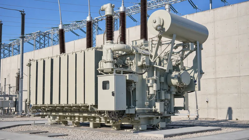
Key takeaways
- A load tap changer (OLTC) varies the turns ratio of a power transformer under load without interrupting continuous secondary current delivery.
- High-speed resistor-type tap changers transition within 40 to 80 milliseconds to minimise contact wear and oil degradation during active switching.
- Modern vacuum-interrupter OLTCs eliminate arcing in dielectric oil, extending mechanical service intervals up to 300,000 operations.
- Regulating winding arrangements—such as linear, reversing (plus/minus), and coarse-fine—dictate physical core footprint, copper losses, and tap range.
- Testing and commissioning of tap changers in transformers must conform to IEC 60214-1 and IEEE C57.131 standards for mechanical and electrical endurance.
Quick answer: A load tap changer is an electro-mechanical or vacuum switching mechanism that alters a transformer turns ratio under active operating conditions, regulating transmission and distribution voltage without disconnecting the load. It adjusts winding taps dynamically to counteract real-time grid fluctuations, maintaining system voltage within statutory limits.
Dynamic voltage regulation is fundamental to modern transmission grids, renewable collector substations, and energy-intensive industrial distribution networks. When grid demand surges or variable renewable generation fluctuates, system voltages drift outside statutory tolerances (typically ±5% or ±10% per IEC 60038). Without dynamic regulation, end-use equipment risks brownouts, overheating, or insulation degradation. A power transformer fitted with a load tap changer (commonly designated an oltc transformer or ltc transformer) solves this challenge by altering the effective number of primary or secondary turns on the fly, eliminating costly plant shutdowns. Understanding the mechanical architecture, electrical commutation principles, and protection interfaces of an oltc tap changer is essential for substation design engineers, procurement teams, and plant asset managers specifying equipment for utility-scale applications.
What Is an On Load Tap Changer OLTC and How Does It Work?
An on load tap changer oltc is an electro-mechanical switching assembly engineered to change physical tapping positions along a transformer winding while carrying continuous, full rated load current. The core mechanical challenge of an active transformer tap changer is moving from one winding tap to another without short-circuiting the adjacent tapping section or breaking the primary load path.
In standard grid applications, the mechanism accomplishes this sequence using two discrete sub-assemblies: the tap selector and the diverter switch (or diverter switch arcing contacts). The tap selector operates off-load in terms of dynamic arc interruption; it mechanically pre-selects the target physical tapping tap contact while no differential voltage is being interrupted. Once the selector contact is firmly seated, the spring-loaded energy accumulator discharges, driving the diverter switch across bridging contacts in tens of milliseconds.
During this bridging interval, transition impedance elements—such as wire-wound resistors or inductive reactors—are brought momentarily into parallel. These transition elements restrict the circulating circulating current ($I_c$) caused by the step voltage ($\Delta U$) across adjacent transformer taps to safe thermal limits. Once the diverter completes its travel, the old tapping point is fully isolated, and the new winding ratio carries 100% of the output load. Modern installations frequently integrate this assembly within an isolated oil compartment or use hermetically sealed vacuum bottles to prevent carbon particles and combustion gases from contaminating the primary dielectric fluid of large power transformers.
Load Tap Changer vs De-Energised Tap Changer (DETC)
The distinction between a load tap changer and a de-energised tap changer (DETC, or off-circuit tap changer) lies in the ability to switch under energised, operational load versus requiring total electrical isolation. Selecting the wrong topology creates severe operational bottlenecks or unnecessary capital expenditure.
A de-energised tap changer requires the upstream and downstream breakers to open before manual or motorised switching occurs. DETCs are standard on lower-voltage distribution units, stepping up or down across a narrow band (typically ±2 × 2.5%) to compensate for permanent seasonal system variations. Conversely, an oltc transformer accommodates rapid voltage fluctuations originating from variable distributed solar, wind ramp rates, and daily industrial load curves. As detailed in our guide to transmission transformer engineering, wide voltage bandwidths and high switching cycles make on-load control mandatory for transmission grid interconnects.
| Design Parameter | De-Energised Tap Changer (DETC) | Load Tap Changer (OLTC) |
|---|---|---|
| Operating Condition | De-energised, fully isolated, zero load | Fully energised, full load current flowing |
| Switching Speed | Manual / slow motor (minutes) | Spring-loaded energy storage (40–80 ms) |
| Typical Regulation Range | ±5% (e.g., 5 positions at 2.5% steps) | ±10% to ±20% (typically 17 to 33 positions) |
| Internal Arc Suppression | None required (zero switching duty) | Vacuum interrupters or transition resistors in oil |
| Capital Cost Multiplier | Baseline (1.0x) | 1.25x to 1.45x total transformer cost |
| Maintenance Interval | Visual check during 5-year outages | 50,000 to 300,000 operations (vacuum vs oil) |
| SCADA / Automation Integration | Rare (manual or basic position indication) | Standard (automatic voltage regulator, RTU link) |
Operating Mechanisms: Resistor Type vs Reactor Type Tap Changers
Industrial and utility tap changers in transformers divide into two primary engineering methodologies: the high-speed transition resistor design (prevalent in IEC markets) and the preventative autotransformer (reactor) design (prevalent in IEEE/ANSI markets).
High-Speed Resistor Tap Changers: Widely applied globally under IEC 60214-1, this mechanism utilises one or two ohmic transition resistors to bridge adjacent taps. Because resistors dissipate continuous energy if left in-circuit, the diverter switch relies on heavy-duty mechanical springs charged by an external motor drive unit. Once tripped, the mechanism completes contact transfer in 40 to 80 milliseconds. The resistors carry current for only 10 to 30 milliseconds, allowing them to remain compact while limiting circulating current to near-nominal load levels. Today, arcing contacts are largely replaced by vacuum interrupter bottles, which contain the switching spark, virtually eliminating contact erosion and oil carbonisation.
Reactor (Preventative Autotransformer) Tap Changers: Common in North American utility specifications governed by IEEE C57.131, reactor-type units utilise a centre-tapped preventive autotransformer winding. Unlike resistor designs, a reactor can remain continuously in service across two adjacent taps without overheating. This property allows bridging positions to serve as legitimate operational service taps. Consequently, an 8-section physical tapping winding can produce 16 operational voltage steps (a 33-position mechanism using 16 physical steps plus neutral). However, reactor OLTCs operate at lower switching velocities and exhibit higher inductive reactive power consumption during bridging, requiring physically larger transformer tank enclosures.
Winding Topologies and Arrangement of Transformer Taps
The mechanical topology of an oltc tap changer is dictated by the arrangement of its regulating winding inside the transformer tank. Specifying engineers must evaluate three primary regulating winding configurations during the design phase: linear, reversing (plus/minus), and coarse-fine regulation.
- Linear Arrangement: The regulating winding is connected directly in series with the main HV phase winding. Taps are tapped off in sequential steps. This topology is simple, robust, and mechanically straightforward, but it requires as many tapping leads and physical switch contacts as there are operational tap positions. It is standard for systems with small regulation ranges (e.g., ±5% across 9 positions).
- Reversing (Plus/Minus) Arrangement: A dedicated reversing switch changes the polarity of the regulating winding relative to the main winding. This doubles the effective regulation range without adding physical turns to the core leg. A 16-step regulating winding yields 32 regulation steps (16 buck positions, 1 neutral, and 16 boost positions). It provides the optimal balance between copper cost and tap changer complexity for standard ±10% utility units.
- Coarse-Fine Arrangement: This topology uses two separate regulating windings: a coarse winding with a large turn count and a fine winding with incremental steps. By engaging or disengaging the coarse winding in conjunction with the fine steps, a wide tap range is achieved with minimal diverter contacts. However, it introduces complex dielectric stresses across the changeover selector, requiring heightened BIL (Basic Lightning Impulse Insulation Level) testing per IEC 60076-3.
For high-voltage systems, the tap changer is virtually always located at the neutral end of a star-connected (wye) high-voltage winding. Placing the load tap changers at the neutral point minimises steady-state dielectric stresses against the grounded tank wall, reducing required clearances and decreasing the physical footprint of the transformer core-and-coil assembly.
Worked Calculation: Tap Step Voltages and Current Rating
Accurate sizing of a load tap changer transformer requires calculating the rated through-current, step voltage, through-power capacity, and transition circulating current to prevent contact welding and thermal breakdown.
Consider a 40 MVA, 115 kV (Primary) to 13.8 kV (Secondary), 3-phase, 50 Hz star-connected (YNd11) transmission substation step-down transformer. The client specification mandates a regulation range of ±10% on the 115 kV high-voltage winding across 16 steps (33 physical operating positions including neutral: 16 boost, neutral, 16 buck).
Step 1: Calculate Rated Primary Full-Load Current ($I_n$)
$$I_n = \frac{S_n}{\sqrt{3} \times U_n} = \frac{40,000\text{ kVA}}{\sqrt{3} \times 115\text{ kV}} = \frac{40,000}{199.19} = 200.82\text{ A}$$
Step 2: Calculate Maximum Tap Current ($I_{max}$) under Full Buck
At the minimum voltage tap position (-10%), the primary system operates at $115\text{ kV} \times (1 - 0.10) = 103.5\text{ kV}$. To transfer full 40 MVA rated capacity without overloading the winding:
$$I_{max} = \frac{40,000\text{ kVA}}{\sqrt{3} \times 103.5\text{ kV}} = \frac{40,000}{179.27} = 223.13\text{ A}$$
The tap changer selected must have a continuous rated through-current ($I_u$) equal to or exceeding 223.13 A; a standard commercial rating of 300 A or 400 A is selected.
Step 3: Calculate Step Voltage ($\Delta U_{step}$)
Total regulation range is 20% across 32 active steps (±10% total span):
$$\text{Step percentage } = \frac{20\%}{32} = 0.625\% \text{ per step}$$
$$\Delta U_{step} = \frac{115,000\text{ V}}{\sqrt{3}} \times 0.00625 = 66,395\text{ V} \times 0.00625 = 414.97\text{ V (phase-to-neutral)}$$
Step 4: Calculate Circulating Current and Transition Resistor Sizing
To limit circulating current during the diverter switch bridging interval to approximately equal rated nominal current ($I_c \approx I_n = 200.82\text{ A}$), we evaluate two transition resistors ($R_t$) placed across the step voltage:
$$I_c = \frac{\Delta U_{step}}{2 \times R_t} \implies R_t = \frac{\Delta U_{step}}{2 \times I_n} = \frac{414.97\text{ V}}{2 \times 200.82\text{ A}} = 1.033\ \Omega$$
Engineers select wire-wound resistors rated at $1.05\ \Omega$ capable of handling a peak bridging pulse power of:
$$P_{pulse} = (I_c)^2 \times R_t = (200.82\text{ A})^2 \times 1.05\ \Omega = 42,345\text{ W (for } 20\text{ ms)}$$
This verification demonstrates that the thermal mass of the transition resistor is well within standard limits of commercial resistor alloys, preventing switch degradation.
OLTC Transformer Protection, Monitoring, and Maintenance
Tap changer failures account for over 25% of all non-lightning-related power transformer outages according to CIGRE reliability surveys. Establishing dedicated mechanical and electrical protection boundaries around the oltc tap changer is essential to system uptime.
Mechanical protection begins with compartmental isolation. The tap changer diverter switch is housed in a separate, sealed oil cylinder inside the main tank. It possesses its own dedicated pressure-relief device (PRD) and a separate, single-float protective relay (similar to a Buchholz relay). As explored in our pillar on substation transformer protection, sudden pressure rises caused by arcing faults inside the tap changer compartment must trip the primary lockout relay (ANSI device 86T) within milliseconds, isolating the unit before tank rupture occurs.
Condition monitoring technologies deployed on critical transmission assets include:
- Dissolved Gas Analysis (DGA) on OLTC Oil: For conventional arcing-in-oil tap changers, significant acetylene ($C_2H_2$) generation is expected; monitoring focuses on sudden spikes in ethylene ($C_2H_4$) which indicate contact overheating. For vacuum-type OLTCs, any presence of acetylene indicates vacuum envelope leakage and requires immediate intervention.
- Dynamic Resistance Measurement (DRM): Conducted during routine testing, DRM measures high-speed contact ripple current during switching to detect open-circuit transitions, bouncing springs, or broken transition resistors.
- Motor Drive Current Profiling: SCADA systems record the current signature of the Motor Drive Unit (MDU). An anomalous current rise flags mechanical binding in the drive shafts, bevel gears, or Geneva wheel mechanisms.
- Online Oil Filtration: Dedicated filtration systems continuously circulate OLTC compartment oil through 1-micron particulate filters to remove free carbon and moisture, preserving dielectric breakdown strength above 50 kV per IEC 60156.
Factory and Field Testing Standards for Load Tap Changers
Factory Acceptance Testing (FAT) and site commissioning of any transformer tap changer must follow stringent test protocols to verify timing synchronization and contact integrity before energisation.
Both IEC 60214-1 (Tap-changers – Part 1: Performance requirements and test methods) and IEEE C57.131 dictate specific routine and type test sequences. Standard commissioning procedures involve a structured multi-step sequence:
- Sequence of Operation Verification: Mechanically cycle the unit across its full operational range from minimum buck to maximum boost position (e.g., tap 1 to tap 33) and back, verifying mechanical end-stop limits, electrical interlocks, and local/remote position telemetry.
- Turns Ratio and Vector Group Verification: Measure the transformer ratio on every individual tap position using a 3-phase TTR (Transformer Turns Ratio) meter to confirm nominal tap step voltages and vector polarity match the design nameplate per IEC 60076-1 clause 10.3.
- Static DC Winding Resistance Measurement: Carry out a winding resistance test across every tapping position. Contact resistance abnormalities indicate misaligned selector contacts or loose tap lead terminations, as detailed in our guide to transformer testing methods.
- Dynamic Contact Timing Analysis: Record switching time oscillograms with an automated tap-changer test set. Transition times must match manufacturer factory specifications within ±10% (typically 40–60 ms total diverter travel, with resistor bridging lasting 15–25 ms).
- Dielectric Breakdown of Compartment Fluid: Sample the dielectric fluid from the OLTC compartment to verify moisture levels fall below 15 ppm and dielectric breakdown voltage exceeds 50 kV (0.08-inch gap).
Engineering Specification and Sourcing Checklist for an LTC Transformer
To prevent costly change orders and project delays during substation execution, technical procurement specifications must precisely state electrical and mechanical requirements for the tap-change equipment.
Engineers preparing an RFQ (Request for Quotation) for an ltc transformer should integrate the following inspection and procurement checklist into their tender schedules:
| Specification Criterion | Engineering Requirement to State | Relevant Reference Standard |
|---|---|---|
| Rated Through-Current | Maximum current carrying capacity at lowest tap voltage including overload margin | IEC 60214-1 cl. 5.2 / IEEE C57.131 |
| Switching Medium | Specify Vacuum Interrupter or Arc-in-Oil contacts | Client Grid Code / Technical Spec |
| Regulating Winding Type | Linear, Reversing (±), or Coarse-Fine configuration | IEC 60076-1 clause 5.4 |
| Step Voltage and Steps | e.g., ±10% in 16 steps (33 operating positions), 0.625% per step | Substation Interconnect Agreement |
| BIL & Dielectric Ratings | Full-wave and chopped impulse ratings for diverter and selector contacts | IEC 60076-3 / IEEE C57.12.00 |
| Motor Drive Unit (MDU) | Auxiliary voltage (AC/DC), local manual crank handle, cabinet IP rating (e.g., IP56) | IEC 60529 / NEMA 4X |
| Controller / AVR Interface | Automatic Voltage Regulator compatibility, IEC 61850 protocol, 4-20 mA tap feedback | IEC 61850-7-4 (LN: ATCC) |
| Oil Preservation System | Separate conservator cell, desiccant breather, dedicated pressure relief device | IEC 60076-22-1 |
Next steps: specifying and sourcing
When specifying high-performance power equipment for utility grids, renewable energy substations, or large industrial plants, matching the duty cycle of your tap-change assembly to site load dynamics is essential. We engineer and manufacture robust oil-immersed transformers and transmission-grade power transformers up to 110 kV fitted with field-proven, low-maintenance vacuum load tap changers built to IEC and IEEE standards. Submit your single-line diagrams, tap range requirements, and station auxiliary voltage specs directly through our transformer quotation portal to receive fully costed engineering proposals and dimensional general arrangement drawings from our design team.
Frequently asked questions
What is the primary difference between an OLTC and a DETC?
An on-load tap changer (OLTC) adjusts transformer turns ratios while the transformer is energised and carrying continuous load current. A de-energised tap changer (DETC) requires the transformer to be completely isolated and de-energised before changing tap positions.
Why is a load tap changer typically placed on the high-voltage winding?
The tap changer is positioned on the high-voltage winding because higher voltage results in lower rated current, allowing for physically smaller contacts and transition elements. Additionally, in star-connected windings, placing taps at the neutral end drastically lowers dielectric insulation clearances to ground.
How long does a load tap changer transition cycle take?
The entire motor-driven tap change operation takes 3 to 6 seconds, but the critical electrical diverter transition takes only 40 to 80 milliseconds. The transition resistors carry bridging circulating current for merely 15 to 25 milliseconds to prevent thermal failure.
What are the advantages of vacuum-type load tap changers?
Vacuum load tap changers contain the switching arc inside hermetically sealed vacuum interrupters, completely preventing arcing products from contaminating the insulating oil. This extends maintenance inspection intervals up to 300,000 operations and dramatically reduces overall lifecycle maintenance costs.
What happens if a load tap changer fails to complete its transition?
If a tap changer stalls during the bridging sequence, transition resistors remain in-circuit and will thermally rupture within seconds due to continuous load current. Protective devices like oil surge relays and compartment pressure switches trip the primary breaker to prevent a violent catastrophic tank failure.
What standards govern the testing and manufacturing of load tap changers?
The two primary international standards are IEC 60214-1 (Tap-changers: Performance requirements and test methods) and IEEE C57.131 (Standard Requirements for Tap Changers on Power Transformers). Overall transformer integration and dielectric clearances follow IEC 60076 and IEEE C57.12.00.
Tags: load tap changer oltc transformer transformer taps tap changer oltc tap changer transformer tap changer


