Key takeaways
- Voltage regulation measures a transformer's percentage change in terminal voltage between no-load and full-load operating conditions.
- The standard voltage regulation formula incorporates per-unit resistance, reactance, and the operating load power factor according to IEC 60076-1 clause 5.4.
- Leading power factors can yield negative voltage regulation, causing receiving-end voltage rise due to the Ferranti effect in capacitive networks and solar collector systems.
- On-load tap changers (OLTC) provide dynamic continuous voltage control under load, whereas de-energised tap changers (DETC) require complete system disconnection.
- Grid codes such as IEEE 1547 and ENTSO-E mandate strict ±5% steady-state voltage bands at the point of common coupling for utility-scale renewable generation.
Quick answer: Transformer voltage regulation is the percentage difference between the secondary terminal voltage at no-load and full-load conditions relative to rated load voltage. It quantifies an electrical system's ability to maintain a constant supply voltage across changing loads, preventing equipment stress and ensuring strict utility grid code compliance.
Maintaining stable voltage profiles across medium-voltage (MV) and low-voltage (LV) networks is fundamental to system efficiency and equipment lifespan. In industrial networks and utility-scale renewable plants, load fluctuations and reverse active power flows introduce severe voltage variations. Designing substations with the correct impedance and tap-changing architecture directly protects downstream assets from under-voltage stalling and over-voltage insulation breakdown.
Voltage Regulation Definition and Governing Principles
A formal voltage regulation definition describes the fractional change in output terminal voltage when a defined electrical load is completely removed while keeping the primary input voltage constant. In practical engineering terms, what voltage regulation means is a direct assessment of internal transformer losses caused by winding winding resistance and leakage reactance.
According to IEC 60076-1 clause 5.4 and IEEE C57.12.00 Table 5, transformer voltage drop is governed by the internal equivalent series impedance ($Z_{eq} = R_{eq} + jX_{eq}$). When current passes through the transformer windings, it creates both an in-phase resistive voltage drop ($I \cdot R$) and a quadrature inductive voltage drop ($I \cdot X$). The vector sum of these drops determines whether terminal voltage sags under lagging industrial inductive loads or swells under leading capacitive loads, such as long underground cable arrays in renewable collector circuits. Proper coordination between substation design and equipment rating, as outlined in our unit substation engineering guide, ensures that terminal variations remain within acceptable operating thresholds.
The Exact Voltage Regulation Formula and Derivation
The mathematical voltage regulation formula compares no-load secondary terminal voltage ($V_{NL}$) with full-load terminal voltage ($V_{FL}$) under defined operating temperatures.
The fundamental voltage regulation equation is expressed as:
$$\%VR = \frac{|V_{NL}| - |V_{FL}|}{|V_{FL}|} \times 100$$
In design engineering and factory acceptance testing, secondary terminal voltages are often pre-calculated using transformer equivalent circuit parameters. When per-unit or percentage resistance (\%R) and percentage reactance (\%X) are known, the simplified Kapp approximation formula evaluates voltage drop across different power factors ($\cos\phi$):
$$\%VR \approx \%R \cos\phi \pm \%X \sin\phi + \frac{(\%X \cos\phi \mp \%R \sin\phi)^2}{200}$$
In this expression:
- Use the positive ($+$) sign for lagging power factors (inductive loads such as motors and conventional manufacturing plants).
- Use the negative ($-$) sign for leading power factors (capacitive systems such as un-energised transmission lines, power factor correction banks, or inverter over-excitation).
- $\%R$ is calculated directly from load loss ($P_k$ in kW) divided by rated power ($S_r$ in kVA) multiplied by 100.
- $\%X = \sqrt{\%Z^2 - \%R^2}$, derived from the total short-circuit impedance (\%Z).
Worked Calculation: Substation Transformer Voltage Regulation
Calculating transformer performance before procurement ensures the unit maintains terminal voltage under peak generation or maximum industrial draw. Consider a 25 MVA, 110 kV to 33 kV step-down utility collector transformer deployed in a wind energy plant.
Transformer Parameters:
- Rated apparent power ($S_r$): 25,000 kVA
- Rated secondary voltage ($V_2$): 33 kV line-to-line
- Short-circuit impedance (\%Z): 10.0%
- Load losses at 75°C ($P_k$): 125 kW
First, calculate percentage resistance (\%R) and percentage reactance (\%X):
$$\%R = \frac{125 \text{ kW}}{25,000 \text{ kVA}} \times 100 = 0.50\%$$
$$\%X = \sqrt{10.0^2 - 0.50^2} = \sqrt{100 - 0.25} = 9.987\%$$
Case 1: Full load at 0.85 lagging power factor ($\cos\phi = 0.85$, $\sin\phi = 0.527$):
$$\%VR = 0.50(0.85) + 9.987(0.527) + \frac{(9.987 \times 0.85 - 0.50 \times 0.527)^2}{200}$$
$$\%VR = 0.425 + 5.263 + \frac{(8.489 - 0.264)^2}{200} = 5.688 + \frac{67.65}{200} = 5.688 + 0.338 = 6.03\%$$
At full lagging load, the secondary voltage drops by 6.03%, bringing the 33.0 kV bus down to 31.01 kV without tap compensation.
Case 2: Full load at 0.95 leading power factor ($\cos\phi = 0.95$, $\sin\phi = 0.312$):
$$\%VR = 0.50(0.95) - 9.987(0.312) + \frac{(9.987 \times 0.95 + 0.50 \times 0.312)^2}{200}$$
$$\%VR = 0.475 - 3.116 + \frac{(9.488 + 0.156)^2}{200} = -2.641 + \frac{93.01}{200} = -2.641 + 0.465 = -2.18\%$$
The negative sign indicates a voltage rise: terminal voltage increases by 2.18% above rated no-load values to 33.72 kV. In high-capacitance renewable generation, this condition demands proactive voltage control.
Voltage Regulating Transformer Equipment: DETC vs OLTC
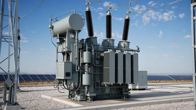
A dedicated voltage regulating transformer incorporates internal tap windings that dynamically alter the turns ratio to offset network voltage drops or swells. Tapping arrangements are configured as either de-energised tap changers (DETC) or on-load tap changers (OLTC) depending on network operational requirements.
The table below contrasts standard tap regulation technologies applied across medium- and high-voltage systems:
| Feature | De-Energised Tap Changer (DETC) | On-Load Tap Changer (OLTC) |
|---|---|---|
| Operational Mode | Manual switching while completely de-energised | Automatic motorized switching under full load current |
| Standard Range | ±2 × 2.5% (5 discrete positions) | ±8 × 1.25% to ±16 × 1.25% (up to 33 steps) |
| System Interruption | Requires complete feeder outage | Continuous power supply with zero interruption |
| Primary Application | Seasonal adjustment, steady industrial distribution | Dynamic grids, renewable generation, fluctuating loads |
| Control Mechanism | Direct manual handle with padlock facility | Microprocessor automatic voltage regulator (AVR) relay |
| Maintenance Cycle | Visual inspection during routine plant shutdowns | Contact wear inspection after 50,000 to 100,000 operations |
Selecting an OLTC increases initial capital investment but is mandatory when integrating variable renewable generators or powering sensitive loads, as detailed in our analysis of grid integration of renewable energy sources.
Voltage Regulation in Renewable Generation and Grid Codes
Grid codes dictate that renewable generation facilities must actively maintain steady-state voltage at the point of common coupling (PCC) within narrow bounds, typically ±5% of nominal voltage under normal conditions and ±10% during contingencies.
In wind and photovoltaic power plants, reverse power flows alter classic distribution dynamics. During peak midday solar generation or strong wind output, power flows back into the transmission network through long medium-voltage collector lines. Because these lines exhibit shunt capacitance and active power injection ($P$), the local bus experiences significant voltage rise rather than drop, according to the standard power flow relationship:
$$\Delta V \approx \frac{P \cdot R + Q \cdot X}{V_n}$$
To prevent over-voltage tripping of utility inverters, modern installations coordinate three systems:
- Inverter Reactive Power Control: Inverters absorb reactive power ($Q < 0$) in accordance with IEEE 1547 and IEEE 2800 grid support functions, counteracting active power voltage rise. Detailed control architecture is explored in our power conversion system guide.
- Transformer Automatic Tap Changers: Substation transformers equipped with OLTCs automatically shift taps downward to absorb excess feeder voltage during peak generation hours, working directly with high-performance power transformers.
- Dynamic Shunt Compensation: STATCOMs or battery storage units provide high-speed reactive injection during rapid wind speed drops or cloud shading events, preventing severe transient voltage sags. Similar collector topology principles are documented in our wind turbine transformer engineering guide.
Engineering Checklist for Specifying Transformer Voltage Regulation
Engineers must provide unambiguous technical requirements in transformer request-for-quotation (RFQ) packages to ensure factory windings and tap changers match site electrical conditions. Use the following structured checklist during project specification:
- Short-Circuit Impedance (%Z): State the nominal impedance and tolerance (typically ±7.5% to ±10% per IEC 60076-1). Specify higher %Z (e.g., 8% to 10%) to limit prospective fault currents, or lower %Z (e.g., 5% to 6%) to minimise intrinsic voltage regulation drop.
- Tap Changer Type and Range: Clearly state whether DETC or OLTC is required. Specify the tapping range (e.g., +10% to -10% in 16 equal steps of 1.25%) on the high-voltage winding.
- Tapping Configuration: Define whether constant flux voltage variation (CFVV) or variable flux voltage variation (VFVV) applies, ensuring core saturation limits are respected under extreme tap settings.
- Automatic Voltage Regulator (AVR) Features: For OLTC units, specify line-drop compensation (LDC), reverse power flow detection capability, SCADA protocol compatibility (IEC 61850 or Modbus TCP), and parallel operation schemes (circulating current or master-follower mode).
- Thermal and Loss Limits: Specify maximum load losses at maximum boost tap positions, as winding currents increase at lower tap voltage steps for a constant MVA throughput.
Next steps: specifying and sourcing
Proper voltage regulation guarantees network reliability, equipment life, and utility compliance. If you are preparing tender specifications or sizing substation equipment for utility, industrial, or renewable plants, early alignment on impedance, tap range, and control architecture prevents costly site modifications. Explore our engineered range of liquid-filled power transformers, custom prefabricated substations, and medium-voltage switchgear assemblies. To review your project one-line diagram or request an engineering consultation, submit your technical requirements through our transformer quote portal or contact our technical team directly via the contact page.
Frequently asked questions
What is the difference between voltage regulation and voltage drop?
Voltage drop is the absolute difference in volts between the sending and receiving ends of a conductor or winding due to impedance. Voltage regulation expresses that change as a percentage relative to rated terminal voltage between no-load and full-load states.
Can transformer voltage regulation be negative?
Yes, voltage regulation is negative when supplying capacitive or leading power factor loads. In this condition, the receiving-end voltage rises above the sending-end voltage due to the Ferranti effect, requiring tap adjustments or reactive power absorption.
Why is low impedance preferred for distribution transformer voltage regulation?
Lower leakage impedance produces lower reactive voltage drop across the transformer windings, resulting in tighter voltage regulation and a more stable output voltage under fluctuating industrial loads.
How does an on-load tap changer maintain voltage regulation?
An on-load tap changer dynamically adjusts the active turns ratio of the transformer winding while carrying load current. Driven by an automatic voltage regulator relay, it shifts taps up or down to keep secondary bus voltage within pre-set limits.
What is the acceptable voltage regulation limit for industrial transformers?
Most industrial and distribution standards design for full-load voltage regulation between 2% and 5% at rated power factor. Auxiliary distribution networks generally aim to keep customer delivery voltages within ±5% of nominal values.
Tags: voltage regulation voltage regulation formula voltage regulating transformer voltage regulation equation transformer design


