Key takeaways
- A low voltage transformer operates at nominal primary and secondary voltages at or below 1,000 V AC according to IEC 60038 and IEEE standards.
- Transformer sizing requires applying continuous duty factors of 125% per NEC Article 450 alongside inrush allowances for high-inductive motor or harmonic switch-mode loads.
- Selecting temperature rise limits of 80°C or 115°C over a 40°C ambient yields lower winding coil losses and longer insulation life compared to standard 150°C Class 220 systems.
- Separately derived systems created by isolation transformers require specific neutral-to-ground bonding jumpers under NEC 250.30 to ensure low-impedance fault clearance.
- Specification documents must establish impedance percentage, enclosure IP or NEMA ratings, sound level thresholds in dBA, and loss validation rules per regional energy standards.
Quick answer: A low voltage transformer is an electrical power conversion unit designed with primary and secondary winding ratings operating at or below 1,000 V AC. Primarily built as dry-type units, these transformers step down facility distribution voltages—such as 480 V or 400 V—to usable service levels like 208Y/120 V or 230 V for lighting, branch circuits, instrumentation, and motor control.
Within modern industrial plants and commercial infrastructures, low-voltage power distribution forms the final conversion tier before electrical energy reaches end-use equipment. Specifying a low voltage transformer requires clear evaluation of thermal insulation classifications, winding impedances, core steel metallurgy, and regional safety mandates including IEC 61558, IEC 60076-11, and UL 1561. Selecting an undersized or improperly protected volt transformer leads to excessive thermal runaway, nuisance primary breaker tripping during magnetising energisation, and accelerated winding degradation caused by third-order harmonics.
What Defines an Industrial Low Voltage Transformer?
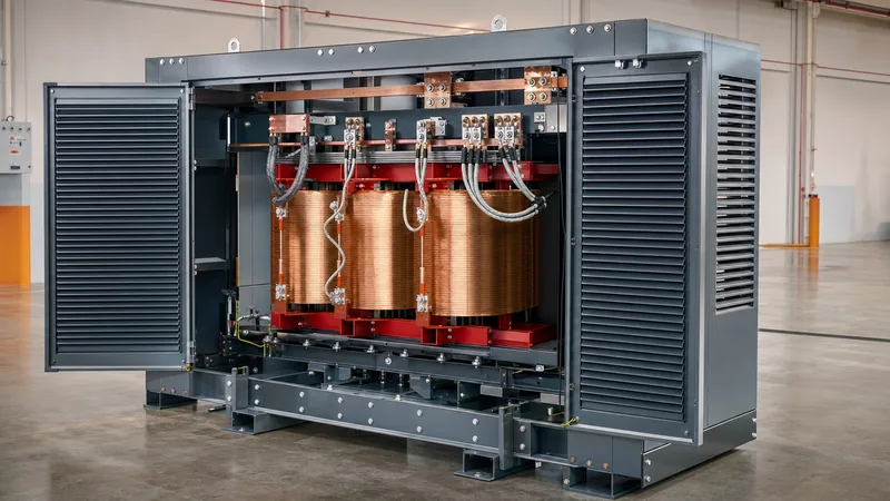
An industrial low voltage transformer provides galvanic isolation and voltage conversion within systems operating below the international 1 kV medium-voltage threshold. Unlike utility-scale power transformers immersed in dielectric mineral oil, standard low-voltage units utilise ventilated dry-type or vacuum-pressure impregnated (VPI) construction. These transformers rely on natural air convection (cooling class AN) or forced-air circulation (AF) to dissipate heat directly to the surrounding ambient environment without liquid containment pits or fire barriers.
Core design employs cold-rolled grain-oriented (CRGO) silicon electrical steel stacked in step-lap configurations. This core geometry minimises no-load eddy currents and hysteretic losses, satisfying efficiency mandates such as US DOE 2016 regulations (10 CFR Part 431) and European Commission EcoDesign Directive 2009/125/EC. Copper or electrical-grade aluminium foil and strip windings are wound around these laminations, vacuum-impregnated with non-hydroscopic polyester or epoxy resins to withstand continuous thermal mechanical stress, humidity, and atmospheric industrial contaminants.
Volt Transformer Topologies: Single-Phase and Three-Phase Configurations
Selecting the right volt transformer configuration depends entirely on the downstream phase balance, load profile, and required system earthing arrangement. Three-phase units represent the standard for facility-wide transformation, commonly configured in a Delta-Wye (Dyn11 or Delta-Y) arrangement. The delta primary isolates third-harmonic zero-sequence currents within the primary mesh, preventing them from propagating into the upstream distribution board, while the grounded secondary wye neutral establishes a stable separately derived source for single-phase phase-to-neutral branch circuits.
Conversely, control power applications rely on a dedicated single-phase volt transformer to step down 480 V or 240 V line power to 120 V or 24 V for safety interlocking, PLC racks, and contactor coils. When evaluating control power feeds or rural utility taps, engineers can review the single phase transformer guide for deep-dive calculations on regulation and instantaneous inrush capacity. In complex installations where switchboards house both main distribution and auxiliary control, integrating matched dry-type transformers directly adjacent to assemblies built to the IEC 61439 low-voltage switchgear standard ensures uniform short-circuit withstand coordination and shared thermal ventilation management.
Sizing Calculation: Worked Engineering Example for a 480 V to 208Y/120 V System
Accurate transformer sizing prevents thermal overheating while controlling starting voltage drops across motor and non-linear loads. Consider an industrial workshop requiring a dedicated step-down transformer to convert a 480 V, 3-phase, 60 Hz feeder to a 208Y/120 V distribution panel. The load profile is calculated as follows:
- Continuous lighting and general socket load: 28 kW at 0.95 power factor lagging
- Non-continuous resistance heating load: 15 kW at 1.0 power factor
- Three-phase motor loads (run current): 35 A full-load current (FLC) at 208 V, 0.85 power factor
- Anticipated future expansion allowance: 20%
The step-by-step sizing calculation follows standard engineering methodology:
- Convert continuous real power to apparent power (kVA):
Continuous load = 28 kW / 0.95 = 29.47 kVA. Applying the mandatory 125% continuous operation factor (NEC Article 450 / 215.2): 29.47 kVA × 1.25 = 36.84 kVA. - Calculate non-continuous real and apparent power:
Heating load = 15 kW / 1.0 = 15.00 kVA. - Calculate motor apparent power:
Motor load kVA = (V × I × √3) / 1,000 = (208 V × 35 A × 1.732) / 1,000 = 12.61 kVA. - Sum base connected load and apply expansion factor:
Subtotal apparent power = 36.84 kVA + 15.00 kVA + 12.61 kVA = 64.45 kVA.
Applying the 20% growth margin: 64.45 kVA × 1.20 = 77.34 kVA.
Standard commercial dry-type transformer ratings follow standardized increments: 45 kVA, 75 kVA, 112.5 kVA, 150 kVA. While 77.34 kVA is close to a 75 kVA rating, running a transformer above its nominal nameplate continuous rating degrades insulation and elevates coil operating temperatures. Consequently, the correct engineering choice is a standard 112.5 kVA transformer. This provides a operating load factor of approximately 68.7%, locating the operating point directly within the peak efficiency band of modern electrical steel cores.
Technical Standards, Impedance and Thermal Performance
A high-performance low voltage transformer must comply with mechanical, dielectric, and loss criteria defined by international standardisation bodies. Key specifications contrast across international IEC frameworks and North American IEEE/UL requirements.
| Engineering Parameter | IEC 60076-11 / IEC 61558-2-4 | UL 1561 / IEEE C57.96 | Engineering Design Impact |
|---|---|---|---|
| Nominal Voltage Limit | Up to 1,000 V AC | Up to 600 V AC | Defines clearance, creepage, and terminal insulation barriers. |
| Standard Insulation Class | Class F (155°C) or Class H (180°C) | Class 220 (220°C) | Determines maximum thermal withstand of winding dielectric varnishes. |
| Standard Temperature Rise | 100 K (Class F) or 125 K (Class H) | 150°C (Standard), 115°C or 80°C (Optional) | Lower rise options (80°C/115°C) cut I²R load losses and handle continuous overloads. |
| Percent Impedance (%Z) | Typically 2.5% to 4.5% | Typically 3.5% to 5.75% | Dictates downstream fault levels and secondary voltage regulation during motor start. |
| Basic Impulse Level (BIL) | 10 kV to 20 kV peak | 10 kV standard (30 kV optional) | Protects windings against transient overvoltages and switching surges. |
| Audible Sound Levels | IEC 60076-10 (45 to 55 dBA typ.) | NEMA standards (45 to 55 dBA typ.) | Essential specification criteria for quiet commercial and hospital settings. |
Selecting an optional 115°C or 80°C temperature rise unit built with Class 220 insulation provides substantial thermal headroom. A 80°C rise transformer operates roughly 70°C cooler than maximum thermal design limits, which reduces facility air-conditioning loads and yields an operational service life exceeding 30 years under full-load industrial duties.
Installation, Grounding and Overcurrent Protection Procedures
Commissioning a low voltage transformer requires adherence to verified physical installation and protective coordination protocols to prevent premature failure. When deploying power distribution units inside complex plants, engineers should reference best practices detailed in our industrial power system installation guide.
- Physical Siting and Vibration Decoupling: Position the transformer enclosure at least 150 mm (6 inches) away from surrounding walls to maintain unrestricted airflow through the ventilation louvres. Secure external flexible conduit connections to eliminate mechanical vibration transmission to the building structure, and ensure internal neoprene vibration isolation pads remain uncompressed by transit lock brackets.
- Separately Derived System Earthing: Install an appropriately sized system bonding jumper between the secondary neutral terminal (X0) and the equipment ground bus within the transformer or at the first downstream disconnect switch. Connect this bus directly to the nearest effectively grounded structural steel, ground electrode conductor, or grounding water pipe per NEC 250.30 or IEC 60364-5-54.
- Primary and Secondary Overcurrent Setting: High inrush currents—ranging from 8 to 12 times rated primary full-load current for 0.1 seconds during core saturation—demand precise protection sizing. Primary-only circuit breakers without secondary protection must generally be set at not more than 125% of primary rated current (or up to 250% where coordinated with feeder fuses under NEC 450.3(B)). When both primary and secondary protection are used, secondary protective devices can be rated up to 125% of rated secondary full-load amps.
- Pre-Energisation Insulation Testing: Perform 1,000 V DC insulation resistance (megohmmeter) testing between primary-to-secondary, primary-to-ground, and secondary-to-ground windings. Acceptable baseline insulation resistance must exceed 100 Megohms at 20°C ambient before closing the line breaker.
Next steps: specifying and sourcing
When preparing a formal request for quotation (RFQ) for an industrial low voltage transformer, provide our engineering department with clear operating parameters: primary and secondary line voltages, required kVA capacity, frequency (50 Hz or 60 Hz), vector group configuration, enclosure ingress protection rating (IP21 up to IP54, or NEMA 1 to 3R/4X), winding conductor metal (copper or aluminium), and non-standard ambient temperature conditions.
Review our specialized manufacturing lines for heavy-duty dry-type transformers or integrate your transformation unit directly into modular HV and LV switchgear assemblies. For complete pricing, detailed structural drawings, and factory loss test data, contact our engineering sales office directly or request a quotation through our transformer quotation portal.
Frequently asked questions
What is the primary difference between a low voltage transformer and a medium voltage transformer?
A low voltage transformer operates with primary and secondary windings rated at or below 1,000 V AC, whereas medium voltage transformers handle primary distribution inputs between 1 kV and 36 kV. Low voltage units are predominantly ventilated dry-type enclosures installed indoors, while medium voltage units are often oil-immersed or cast resin.
Can a step-down low voltage transformer be reverse-fed as a step-up transformer?
Yes, standard dry-type transformers can generally be reverse-fed, but doing so increases inrush currents significantly because the inner winding is energised first. Furthermore, standard turns ratios include compensation for internal impedance voltage drop, meaning reverse feeding typically yields an output voltage roughly 2% to 4% lower than nominal nameplate calculations.
Why should I specify an 80°C or 115°C temperature rise transformer instead of a standard 150°C unit?
Specifying an 80°C or 115°C temperature rise with Class 220 insulation uses larger conductors and superior core materials, cutting internal electrical I²R losses by 15% to 30%. This substantially reduces operating energy costs, lowers switchgear room heat loads, and extends winding insulation lifespan under continuous full-load conditions.
What causes loud humming noise in a low voltage transformer?
Transformer hum is caused by magnetostriction, where alternating magnetic flux lines mechanically expand and contract the core silicon steel laminations at twice line frequency (100 Hz or 120 Hz). Excessive noise is typically caused by unloosened transit shipping brackets, loose core clamping bolts, harmonic load distortion, or operating above nominal primary tap voltages.
How does non-linear load harmonics impact low voltage transformer sizing?
Non-linear electronic loads create high-frequency harmonic currents that cause eddy-current losses in windings and stray load losses in core clamping steel to spike exponentially. When feeding high-harmonic loads like variable speed drives or computing power supplies, engineers must specify K-factor rated transformers (such as K-4, K-13, or K-20) or heavily derate conventional units.
Tags: low voltage transformer volt transformer dry type transformer power distribution electrical engineering


