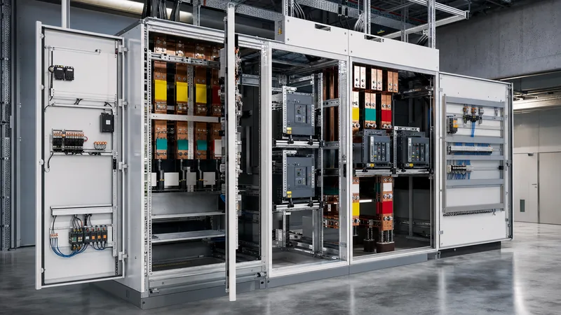
Key takeaways
- IEC 61439 replaces the obsolete TTA/PTA classification of IEC 60439 with a unified design verification framework comprising 13 distinct compliance requirements.
- The standard legally divides obligations between the Original Manufacturer who proves the reference design and the Assembly Manufacturer who builds the final panel.
- Forms of internal separation (Form 1 through Form 4b) define physical metal or non-metallic partitions between busbars, functional units, and external terminals.
- Temperature rise verification under Clause 10.10 requires testing or numerical calculation using rated diversity factors to ensure busbars and terminals stay within material thermal limits.
- Clause 11 mandates ten non-negotiable routine verifications on 100% of manufactured low-voltage panels before factory dispatch.
Quick answer: IEC 61439 is the international safety and performance standard governing low-voltage switchgear and controlgear assemblies up to 1,000 V AC (1,500 V DC). It establishes technical benchmarks for electrical protection, temperature rise, mechanical strength, and short-circuit withstand across industrial and commercial power distribution.
First published by the International Electrotechnical Commission to replace the legacy IEC 60439 series, this standard eliminated ambiguous classifications such as Type-Tested Assemblies (TTA) and Partially Type-Tested Assemblies (PTA). In modern power engineering, specifying a switchboard requires a rigorous design verification process governed by technical evidence rather than arbitrary builder certifications. From primary distribution switchboards feeding industrial processes to motor control centres (MCCs) in heavy industry, compliance with this standard guarantees that an assembly will safely handle continuous load currents, isolate transient fault events, and safeguard operational personnel against catastrophic mechanical and thermal failures.
Understanding the architecture of this benchmark is essential for electrical consultants, plant engineers, and EPC contractors procuring distribution hardware. Integrating low-voltage assemblies downstream of distribution transformers or medium-voltage infrastructure—such as systems detailed in our electrical switchgear engineering guide—demands strict alignment with its definitions, structural forms of separation, and rated operating parameters.
What is the IEC Standard for LV Panels? (Architecture of IEC 61439)
The governing international standard for low-voltage panels is the IEC 61439 series, structured as a modular set of documents that pair general design rules with assembly-specific application parts.
Specifiers asking "what is the IEC standard for LV panels?" must look beyond a single document. The suite consists of Part 1, which establishes universal mechanical, electrical, and thermal criteria, combined with an application-specific secondary part that tailors requirements to the end-use environment:
- IEC 61439-1 (General rules): The foundation document containing shared definitions, service conditions, constructional requirements, and verification protocols. It cannot be used alone to certify a panel; it must always be applied in conjunction with the relevant product part.
- IEC 61439-2 (Power switchgear and controlgear assemblies - PSC-assemblies): Covers industrial switchboards, main distribution boards, and motor control centres intended primarily for industrial and commercial facilities operated by skilled or instructed persons.
- IEC 61439-3 (Distribution boards): Regulates distribution boards intended to be operated by ordinary persons (non-professionals), such as consumer units and sub-distribution panels in public buildings or residential environments, with rated current to earth ($I_n$) limited to 250 A and outgoing circuits capped at 125 A.
- IEC 61439-4 (Assemblies for construction sites): Specifies temporary switchgear subjected to extreme vibration, weather exposure, and severe duty cycles.
- IEC 61439-5 (Assemblies for power distribution in public networks): Regulates outdoor feeder pillars, substation distribution panels, and cable distribution cabinets installed in utility networks.
- IEC 61439-6 (Busbar trunking systems / Busways): Covers prefabricated bus duct trunking used to distribute high-current feeds through industrial plants and high-rise commercial structures.
- IEC TR 61439-7 (Electric vehicle charging, marinas, and campsites): A technical report detailing specific guidelines for public supply assemblies in specialised environments.
By splitting the standard into universal rules and targeted applications, the framework ensures identical electrical fundamentals apply whether you are installing a compact commercial distribution panel or integrating high-fault-level switchboards within a containerised substation alongside metal-clad switchgear.
Original Manufacturer vs Assembly Manufacturer Responsibilities
The standard establishes a clear legal and technical demarcation between two distinct entities: the Original Manufacturer and the Assembly Manufacturer.
Prior to this standard, switchboard builders frequently modified factory-tested modular designs without retesting, leading to unverified thermal risks and inadequate fault withstand ratings. Clause 3.10 of Part 1 eliminates this loophole by assigning specific technical duties:
The Original Manufacturer (Clause 3.10.1): The organisation that completes the original design and fully verifies an assembly system in accordance with the 13 design verification requirements of Clause 10. This entity produces the technical documentation, catalogues, busbar topologies, structural blueprints, and derating tables. They bear the sole technical responsibility for carrying out laboratory type tests or certified structural calculations that prove the safety envelope of the enclosure system and its modular components.
The Assembly Manufacturer (Clause 3.10.2): The organisation that takes the proven design system from the Original Manufacturer and completes the assembly, mechanical fitting, electrical wiring, and integration of switching devices to produce the final, operational switchboard. The Assembly Manufacturer may be an independent panel builder, a system integrator, or an EPC contractor's fabrication workshop.
If the Assembly Manufacturer builds the switchboard strictly according to the detailed rules, mechanical arrangements, and component lists validated by the Original Manufacturer, they only need to perform the routine verifications listed in Clause 11. However, if the Assembly Manufacturer deviates from the Original Manufacturer's tested envelope—by introducing alternative busbar configurations, swapping circuit breakers for unverified equivalents, altering enclosure ventilation slots, or expanding current ratings—they automatically assume the full legal obligations of the Original Manufacturer. Consequently, they must independently verify those modified characteristics using Clause 10 test protocols before affixing the rating plate.
IEC 61439 Design Verification: The 13 Mandatory Checks
Design verification under Clause 10 mandates that every structural, electrical, and thermal characteristic of a switchgear assembly must be validated using one or more of three approved routes: testing, calculation, or application of design rules.
The standard explicitly dictates which verification methods are legally admissible for each performance characteristic. Substitution of testing with simple calculation is strictly forbidden for complex phenomena such as arc containment or mechanical impact.
| Verification Characteristic | IEC 61439-1 Clause | Available Verification Options | Critical Engineering Acceptance Criteria |
|---|---|---|---|
| Strength of materials and parts | Clause 10.2 | Testing | IK code verification (IEC 62262), thermal stability, resistance to UV, rust resistance (salt spray test per ISO 9227). |
| Degree of protection (IP rating) | Clause 10.3 | Testing | Compliance with IEC 60529; prevents ingress of solid objects, dust, and water across external envelopes and partitions. |
| Clearances and creepage distances | Clause 10.4 | Testing or Measurement | Rated impulse withstand ($U_{imp}$) clearances verified by physical measurement or high-voltage impulse testing ($1.2/50\ \mu\text{s}$). |
| Protection against electric shock | Clause 10.5 | Testing or Calculation | Earth continuity testing (< 0.1 $\Omega$ at 10 A test current) between all exposed conductive parts and the main protective earthing conductor. |
| Incorporation of switching devices | Clause 10.6 | Design rules | Checking device suitability against application duty, correct placement, mechanical coordination, and access clearances. |
| Internal electrical circuits and connections | Clause 10.7 | Design rules | Correct torque-tensioning, conductor cross-sections, insulation classes, and mechanical restraint of cabling against fault forces. |
| Terminals for external conductors | Clause 10.8 | Testing or Design rules | Adequate physical wire-bending space, wire pull-out strength, and conductor clamping capacity for copper or aluminium cables. |
| Dielectric properties | Clause 10.9 | Testing | Power-frequency withstand voltage ($2 U_i + 1000\text{ V AC}$, minimum 1890 V AC for 1 minute) and impulse withstand tests. |
| Temperature rise limits | Clause 10.10 | Testing, Calculation, or Derivation | Maximum temperature limits on copper busbars (105°C bare, 120°C insulated), terminals (typically 70 K rise), and outer surfaces. |
| Short-circuit withstand strength | Clause 10.11 | Testing or Derivation | Validation of busbar support spacing, dynamic electromagnetic deflection, and thermal withstand ($I_{cw}$ and $I_{pk}$). |
| Electromagnetic compatibility (EMC) | Clause 10.12 | Testing or Design rules | Immunity to transient overvoltages and emission suppression under Environment A (industrial) or Environment B (commercial). |
| Mechanical operation | Clause 10.13 | Testing | 200 mechanical operating cycles for racking mechanisms, drawout cassettes, mechanical interlocks, and door hinges. |
Understanding these 13 criteria enables specifiers to interrogate manufacturer documentation, rejecting substandard bids supported only by generic component datasheets rather than assembly-level verification.
Forms of Internal Separation Under IEC 61439-2
Forms of internal separation describe the physical barriers installed within a low-voltage switchgear assembly to isolate busbars, functional units, and connection terminals from one another.
IEC 61439-2 Clause 8.101 outlines these structural configurations, designated as Form 1 through Form 4. The primary objective is to safeguard maintenance personnel against accidental contact with live components in adjacent compartments, limit the propagation of internal arc faults, and prevent metallic debris dropped in one compartment from causing a catastrophic flashover elsewhere in the board. Mitigation of arc energy is closely tied to the principles explained in our guide to arc flash safety and switchgear design.
- Form 1: No internal separation. The busbars, circuit breakers, control modules, and cable terminals share a common open compartment inside the external enclosure. Form 1 offers the lowest cost and footprint but provides no physical isolation during maintenance.
- Form 2: Separation of the main horizontal and vertical busbars from the functional units (circuit breakers, motor starters):
- Form 2a: Terminals for external conductors are not separated from the busbars.
- Form 2b: Terminals for external conductors are physically separated from the main busbars.
- Form 3: Separation of the main busbars from functional units, and separation of all functional units from one another. External cable connection terminals remain unseparated from each other:
- Form 3a: External cable terminals are not separated from the main busbars.
- Form 3b: External cable terminals are physically separated from the main busbars, but grouped together in a common cabling compartment.
- Form 4: Separation of the busbars from functional units, separation of all functional units from one another, and complete separation of the external cable connection terminals associated with each individual functional unit:
- Form 4a: Terminals for external conductors are located within the exact same individual compartment as the associated functional switching device.
- Form 4b: Terminals for external conductors are housed in their own dedicated, segregated compartment or glanding chamber, isolated from both the functional unit and adjacent outgoing circuits.
For heavy industrial installations, such as continuous chemical processing plants, water utilities, and mining, Form 4b is universally specified. It allows technicians to pull and terminate new field cables into an isolated cable compartment while adjacent outgoing circuits and the main busbars remain fully energized, minimising unplanned plant downtime.
Temperature Rise Limits and Practical Sizing Calculations
Temperature rise verification ensures that electrical power assemblies do not exceed thermal limits that cause insulation degradation, terminal oxidation, or nuisance breaker tripping under continuous full-load conditions.
Under IEC 61439-1 Clause 10.10, the temperature rise of an assembly is evaluated against a standard ambient temperature profile: a maximum ambient of 40°C, a daily 24-hour average of no more than 35°C, and an annual average of 25°C. Any installation in hotter operating environments (such as Middle Eastern desert sites or poorly ventilated modular buildings) requires engineering derating of copper conductors and protective switchgear.
The standard allows temperature rise verification through three primary routes: full-scale physical thermal testing, derivation from tested reference designs, or calculation using the thermodynamic methods of IEC 60890 (valid for assemblies with a rated current up to 1,600 A, or up to 630 A where internal air circulation is fully natural).
Worked Calculation Example: Total Heat Dissipation in an LV Compartment
Consider an enclosed, naturally cooled Form 4b motor control cubicle containing one main incoming 800 A Air Circuit Breaker (ACB) and three 160 A Moulded Case Circuit Breakers (MCCBs) feeding continuous industrial pumps. The engineering team must calculate total internal heat generation to verify that internal air temperatures do not exceed the 65°C operating threshold for electronic trip units.
- Determine Component Heat Losses ($P_{devices}$): Consult device manufacturer datasheets at continuous rated operating current:
- One incoming 800 A ACB dissipates 140 W per pole at rated current. For a 3-pole breaker operating at 700 A actual load: $P_{ACB} = 3 \times 140 \times \left(\frac{700}{800}\right)^2 = 321.56\text{ W}$.
- Three 160 A MCCBs each dissipate 18 W per pole at 160 A. With each pump operating at 120 A continuously: $P_{MCCB} = 3 \text{ units} \times 3 \text{ poles} \times 18\text{ W} \times \left(\frac{120}{160}\right)^2 = 91.13\text{ W}$.
- Total switching device dissipation: $P_{devices} = 321.56 + 91.13 = 412.69\text{ W}$.
- Determine Conductor and Busbar Losses ($P_{conductors}$): Under IEC 61439-1 Clause 10.10.4.2, conductor losses are typically estimated at 20% to 30% of total switching equipment dissipation unless detailed $I^2R$ calculations for copper busbar runs and droppers are performed:$$P_{conductors} = 0.25 \times P_{devices} = 0.25 \times 412.69 = 103.17\text{ W}$$
- Sum Total Heat Generation ($P_{total}$):$$P_{total} = P_{devices} + P_{conductors} = 412.69 + 103.17 = 515.86\text{ W}$$
- Calculate Enclosure Effective Cooling Surface Area ($A_e$): Using an enclosure measuring 2,200 mm high, 800 mm wide, and 800 mm deep, installed against a wall with free top and sides (per IEC 60890):$$A_e = 1.4 \times W \times (H + D) + 1.8 \times D \times H$$$$A_e = 1.4 \times 0.8 \times (2.2 + 0.8) + 1.8 \times 0.8 \times 2.2 = 3.36 + 3.168 = 6.528\text{ m}^2$$
- Calculate Internal Air Temperature Rise ($\Delta T_{air}$): Applying the simplified steady-state cooling constant for painted sheet steel enclosures ($k \approx 4.5\text{ W}/(\text{m}^2 \cdot \text{K})$):$$\Delta T_{air} = \frac{P_{total}}{k \times A_e} = \frac{515.86}{4.5 \times 6.528} = 17.56\text{ K}$$
With a maximum site ambient temperature of 40°C, the estimated internal compartment temperature is $40°C + 17.56°C = 57.56°C$. Because this value remains safely below the 65°C limit for internal electronics, standard natural ventilation grilles are technically acceptable without requiring forced extraction fans.
Short-Circuit Withstand Strength and Mechanical Bracing
Clause 10.11 mandates that the structural framework, busbar holders, and conductor profiles within an assembly must endure the mechanical and thermal stresses generated by short-circuit faults without losing structural integrity or flashover clearances.
A short-circuit event produces two distinct physical phenomena that must be accounted for during design verification:
- Thermal Stresses (Short-time withstand current, $I_{cw}$): Measured in r.m.s. kiloamperes for a specified duration (normally 1.0 or 3.0 seconds). The energy dissipated ($I_{cw}^2 \cdot t$) raises the temperature of the busbars rapidly. The cross-sectional area of the copper or aluminium busbars must be large enough to prevent the metal from reaching annealing temperatures that cause physical softening or terminal creep.
- Electrodynamic Stresses (Peak withstand current, $I_{pk}$): The instantaneous crest value of the fault waveform during the first sub-transient peak. The mechanical repulsive force ($F$) exerted between adjacent parallel rectangular busbars is proportional to the square of this peak current and inversely proportional to the center-to-center distance ($d$) between phases:$$F = \frac{\mu_0}{2\pi} \cdot \frac{I_{pk}^2}{d} \cdot L$$Where $\mu_0$ is the magnetic permeability of air ($4\pi \times 10^{-7}\text{ H/m}$) and $L$ is the unsupported length of the busbar span between insulating supports.
If busbar supports are placed too far apart, electrodynamic repulsion will deflect the copper bars, shattering polymer supports, fracturing insulator mounts, and potentially causing phase-to-phase short-circuits. Standard $I_{pk}$ to $I_{cw}$ conversion ratios are defined in IEC 61439-1 Table 7 based on the short-circuit power factor ($\cos\phi$):
- For $I_{cw} \le 20\text{ kA}$: $n = 1.7$ ($I_{pk} = 1.7 \times I_{cw}$)
- For $20\text{ kA} < I_{cw} \le 50\text{ kA}$: $n = 2.1$ ($I_{pk} = 2.1 \times I_{cw}$)
- For $I_{cw} > 50\text{ kA}$: $n = 2.2$ ($I_{pk} = 2.2 \times I_{cw}$, corresponding to an electrical system with a highly inductive power factor of 0.20 or lower).
Coordination with upstream protective devices—such as circuit breaker instantaneous trip characteristics and protection schemes discussed in our substation protection engineering guide—allows engineers to use conditional short-circuit ratings ($I_{cc}$) where short-circuit withstand is bounded by an upstream current-limiting fuse or fast-acting circuit breaker.
Clearances, Creepage Distances, and Dielectric Requirements
Clearance and creepage distances govern the physical spacing required between live conductors and earthed frames to prevent dielectric breakdown under steady-state operating voltages and transient switching surges.
IEC 61439-1 Clause 10.4 cross-references the insulation coordination rules of IEC 60664-1. Spacing requirements depend on three primary criteria:
- Rated Impulse Withstand Voltage ($U_{imp}$): The peak transient voltage the assembly can withstand without flashover during switching events or atmospheric lightning strikes. Standard ratings for LV switchboards are typically 6 kV, 8 kV, or 12 kV. For a 8 kV $U_{imp}$ rating under inhomogeneous field conditions (Case A), Clause 8.3.2 specifies a minimum absolute physical clearance in air of 8.0 mm.
- Rated Insulation Voltage ($U_i$) and Pollution Degree: Creepage is the shortest path along the surface of a solid insulating material between two conductive parts. It depends on the pollution degree of the installation environment (typically Pollution Degree 3 for industrial environments, representing conductive pollution or dry non-conductive pollution that becomes conductive due to condensation).
- Comparative Tracking Index (CTI): The insulating material's resistance to electrical tracking across its surface. Materials are categorised into Material Groups I ($600 \le \text{CTI}$), II ($400 \le \text{CTI} < 600$), IIIa ($175 \le \text{CTI} < 400$), and IIIb ($100 \le \text{CTI} < 175$).
For a switchboard with a rated insulation voltage ($U_i$) of 1,000 V AC operating in a Pollution Degree 3 industrial environment with Material Group IIIa busbar supports (such as standard glass-reinforced polyester), the absolute minimum creepage distance across the insulator surface is 16.0 mm. Failure to maintain this spacing results in surface carbonisation tracking and catastrophic phase-to-phase flashovers under humid conditions.
Routine Verification Checklist for Factory Acceptance Testing (Clause 11)
Clause 11 mandates ten distinct routine verifications that must be performed by the Assembly Manufacturer on every individual switchboard section produced before it leaves the factory floor.
Unlike design verification (which is performed on representative prototypes or verified by design rules), routine verification is 100% non-destructive and must be formally documented in a Factory Acceptance Test (FAT) record:
- Degree of protection of enclosures (Clause 11.2): Visual inspection confirming all gland plates, door gaskets, blanking plates, and ventilation louvres comply with the target IP rating (e.g., IP54 or IP42) without gaps or distorted sheet metal.
- Clearances and creepage distances (Clause 11.3): Measurement of conductor spacing at terminals, busbar joints, and breaker connections to confirm they meet minimum design distances.
- Protection against electric shock and integrity of protective circuits (Clause 11.4): Verification that all hinged doors, structural covers, and gland plates are bonded to earth. The resistance of the protective circuit between any accessible metal part and the main earthing terminal must not exceed 0.1 $\Omega$.
- Incorporation of built-in components (Clause 11.5): Checking that installed switchgear, fuses, instrument transformers, and surge arresters match the approved single-line diagram and engineering bill of materials.
- Internal electrical circuits and connections (Clause 11.6): Torque auditing of busbar bolted joints using a calibrated torque wrench, verification of mechanical crimps on flexible wiring, and checking randomized wire pull-out tension.
- Terminals for external conductors (Clause 11.7): Inspecting outgoing power terminals to confirm adequate cross-sectional cable entry area and mechanical fastening capacity.
- Mechanical operation (Clause 11.8): Functional testing of all mechanical interlocks, door latches, racking mechanisms for withdrawable circuit breakers, and padlocking systems.
- Dielectric properties (Clause 11.9): Performing high-voltage power-frequency withstand testing at the test voltage specified in Table 8 or Table 9 (typically 1,890 V AC or 2,500 V DC for 1 second between phases and to earth), or insulation resistance testing at 500 V DC showing an insulation resistance of at least 1,000 $\Omega/\text{V}$.
- Wiring, operational performance, and electrical function (Clause 11.10): Energising auxiliary control circuits to verify the correct sequence of control relays, PLC interlocking logic, breaker shunt trip operation, emergency stop circuits, and protective relay signaling.
- Marking and documentation (Clause 11.1): Verifying that the permanent rating plate is fixed, legible, and contains the required nameplate data including the Assembly Manufacturer's name, serial number, standard designation (IEC 61439-2), rated operational voltage ($U_e$), and short-circuit rating ($I_{cw}/I_{pk}$).
Next Steps: Specifying and Sourcing Compliant Switchboards
Procuring fully verified low-voltage switchgear requires clear technical documentation to eliminate ambiguity between specifiers and panel builders during tender evaluations.
When preparing an inquiry or Request for Quotation (RFQ), provide the following parameters upfront: single-line diagrams showing rated operational voltage ($U_e$), required short-circuit ratings ($I_{cw}$ for 1 s and $I_{pk}$), internal separation Form (e.g., Form 3b or Form 4b), ingress protection class (IP rating), installation site ambient conditions, and outgoing cable sizes. Specify that the supplier must furnish Clause 10 design verification certificates from an accredited laboratory alongside the completed Clause 11 routine test certificates.
Explore our engineered HV and LV switchgear solutions and integrated prefabricated transformer substations to view designs certified to international performance benchmarks. To submit your electrical single-line diagrams, engineering specifications, or equipment schedules for a technical review and quotation, visit our switchgear quotation portal.
Frequently asked questions
what is the iec standard for lv panels
The primary international standard for low-voltage panels is the IEC 61439 series, specifically IEC 61439-1 (General rules) paired with IEC 61439-2 for industrial switchgear and controlgear assemblies. It covers assemblies operating at up to 1,000 V AC and defines mandatory safety, short-circuit, thermal, and mechanical performance requirements.
What is the difference between IEC 60439 and IEC 61439?
IEC 61439 completely replaced the obsolete IEC 60439 series, eliminating the outdated Type-Tested Assembly (TTA) and Partially Type-Tested Assembly (PTA) categories. Instead, it introduces a single, verified design framework requiring proof of 13 specific design criteria via testing, standardized calculation, or strict design rules.
What is the difference between Form 2, Form 3, and Form 4 separation?
Form 2 separates the main busbars from functional units. Form 3 adds separation between the functional units themselves, while grouping cable terminals together. Form 4 provides total separation between busbars, functional units, and individual cable termination compartments for every outgoing circuit.
Can calculation replace physical testing under IEC 61439?
Calculation can only replace physical testing for specific characteristics, such as temperature rise (limited to assemblies under 1,600 A per IEC 60890) and low-level short-circuit withstand derivation. Critical properties like degree of protection (IP rating), mechanical impact (IK rating), and internal arc mitigation must always be physically tested.
What is rated diversity factor (RDF) under IEC 61439?
Rated diversity factor (RDF) is the numerical fraction of continuous rated current that an assembly's outgoing circuits can carry simultaneously without exceeding temperature rise limits. Unless specified otherwise by the buyer, the manufacturer defines the RDF (typically between 0.6 and 0.9) based on verified thermal loading calculations.
Tags: iec 61439 lv switchgear switchboard design forms of separation routine verification


