Key takeaways
- A ratio tester measures the true no-load voltage ratio between primary and secondary windings to detect internal winding faults, shorted turns, and tap-changer misalignments.
- International standards IEC 60076-1 and IEEE C57.12.00 mandate that the measured turns ratio must not deviate by more than plus or minus 0.5 percent from the nameplate value.
- Modern three-phase transformer turns ratio testers simultaneously measure turns ratio, excitation current, and phase angle displacement to confirm vector group configurations.
- Excitation current evaluation during a ratio test provides critical early-stage detection of core lamination degradation and partial inter-turn short circuits.
- Routine turns ratio testing across all tap positions verifies mechanical switch integrity before commissioning or following major system fault events.
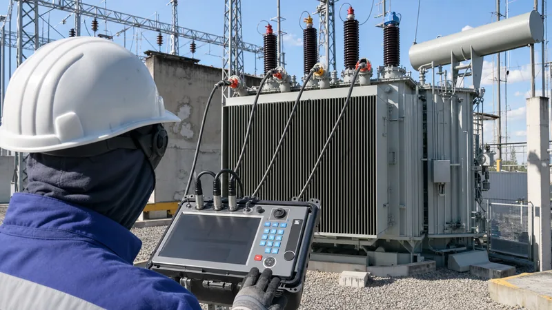
Quick answer: A ratio tester (often called a transformer turns ratio tester or TTR) is a specialised diagnostic instrument designed to measure the precise voltage and turns ratio between the primary and secondary windings of a transformer under no-load conditions. It confirms winding integrity, detects shorted turns or open circuits, and verifies that the manufactured unit adheres to the required design specifications.
During both factory acceptance testing (FAT) and field commissioning, verifying the precise turns relationship between high-voltage (HV) and low-voltage (LV) windings is vital for electrical asset management. Even a single shorted turn alters magnetic balance, degrades thermal dissipation, and induces circulating fault currents that can destroy equipment. When evaluating electrical assets using our Transformer Sizing Calculator: Complete Engineering Guide, specifying accurate turns ratios ensures the operational efficiency, correct voltage delivery, and safe parallel operation of distribution and power transformers.
What Is a Transformer Turns Ratio Tester and How Does It Work?
A transformer turns ratio tester determines the mathematical quotient of primary winding turns to secondary winding turns by applying an AC excitation voltage to one winding and measuring the induced voltage across the corresponding winding.
The underlying principle is governed by Faraday's law of electromagnetic induction. In an ideal transformer, the turns ratio ($N_p / N_s$) equals the voltage ratio ($V_p / V_s$). In a real unit, magnetic flux leakage and excitation losses cause minor deviations, but no-load conditions permit high-precision measurements. For deep theoretical background, see our dedicated guide on the Transformer Turns Ratio Formula: Engineering Guide & Calculations.
Modern digital instruments apply a low, regulated test voltage (typically between 8 V AC and 250 V AC at power frequencies of 50 Hz or 60 Hz) to the high-voltage winding. This step-down configuration avoids generating dangerously high voltages on the opposing terminals. Highly accurate internal potential dividers and microprocessor-controlled digital voltmeters read the primary excitation and secondary output simultaneously, computing the ratio ($N_1 / N_2$) to four or five decimal places.
Advanced three-phase test sets do not simply measure single-phase scalar magnitudes. They capture phase angle displacement ($ heta$), identifying phase shifts introduced by vector groups such as Dyn11, YNd1, or Dd0. They also record the magnetising or excitation current ($I_{exc}$), which serves as a sensitive indicator of core laminations, loose windings, or magnetic asymmetry.
Standard Tolerances and Technical Specifications Under IEC and IEEE
International standards specify strict tolerances for turns ratio measurements to ensure system compatibility and prevent circulating currents between paralleled transformers.
According to IEC 60076-1 (Power Transformers - Part 1: General), the measured voltage ratio on the principal tapping between any two windings must not differ from the declared ratio by more than ±0.5%. For subsequent tap positions, the standard permits either ±0.5% or a value equal to one-tenth of the actual percentage impedance on that tap, whichever is lower. The North American standard IEEE C57.12.00 enforces an identical ±0.5% tolerance limit across all taps.
The technical parameters of a commercial-grade transformer turns ratio meter must substantially exceed the transformer's tolerance limits to guarantee measurement validity. The table below outlines standard instrument capabilities required for rigorous industrial and substation acceptance testing:
| Technical Parameter | Standard Bench/Field Specification | Engineering Significance |
|---|---|---|
| Ratio Measurement Range | 0.8 to 15,000:1 | Accommodates low-ratio distribution units through 500 kV transmission units |
| Measurement Accuracy | ±0.05% to ±0.1% of reading | Five to ten times more precise than the ±0.5% pass/fail standard threshold |
| Excitation Test Voltage | 8 V, 40 V, 100 V, 250 V AC | Selectable to prevent core saturation while energising high-impedance windings |
| Excitation Current Range | 0 to 2 A (resolution down to 0.1 mA) | Measures core magnetization patterns and uncovers shorted turns |
| Phase Angle Range | 0 to 360 degrees (±0.1° accuracy) | Verifies winding polarity, vector group, and internal lead connections |
| Standard Compliance | IEC 61010-1, IEEE C57.12.90 | Guarantees operator safety and standardised test methods |
Step-by-Step Procedure for Operating a Ratio Tester in the Field
Operating a ratio tester requires rigorous safety protocols, precise lead connections, and methodical execution across every tap position.
Before commencing tests during commissioning or routine predictive maintenance, refer to our comprehensive procedures in How to Test a Transformer: Field and Factory Testing Guide. Follow this numbered sequence when testing distribution or transmission assets:
- Isolate and Ground: Fully de-energise the transformer. Disconnect all primary, secondary, and neutral bushings from external busbars and cables. Apply temporary safety grounds to discharge residual electrostatic capacitance before removing them for testing.
- Establish Instrument Ground: Connect the dedicated safety ground terminal of the ratio tester directly to the substation earth grid or transformer tank ground lug.
- Connect Test Leads: Attach the high-voltage test cables (marked H1, H2, H3, H0) securely to the transformer high-voltage bushings. Connect the low-voltage cables (marked X1, X2, X3, X0) to the corresponding low-voltage bushings. Ensure clamp jaws bite cleanly through surface oxidation.
- Configure Nameplate Parameters: Input the transformer vector group, rated primary line-to-line voltage, rated secondary line-to-line voltage, and number of tap changer positions into the instrument interface.
- Execute Principal Tap Test: Initiate the test cycle at the nominal tap position. The instrument energises the HV winding, acquires the induced LV signals, and displays ratio, percentage error, phase displacement, and excitation current.
- Sweep All Tap Positions: Cycle the off-circuit tap changer (OCTC) or on-load tap changer (OLTC) sequentially through all tap steps from lowest to highest, executing a test cycle at each position to verify ratio linearity.
- Record and Discharge: Save the dataset to the internal memory, verify the automatic discharge sequence completes, switch off the instrument, and ground all transformer bushings before disconnecting leads.
Diagnosing Faults with a Transformer Turns Ratio Meter
A transformer turns ratio meter serves as an exceptional diagnostic tool, pinpointing internal mechanical and electrical defects that simple continuity checks cannot identify.
When a ratio test fails the ±0.5% threshold, the specific nature of the numerical discrepancy reveals the underlying failure mode:
- Inter-Turn Short Circuits: When insulation breaks down between adjacent winding turns, the effective turn count drops. A shorted turn produces an abnormal ratio reading accompanied by a massive increase (often 5 to 20 times normal) in excitation current, caused by severe magnetic coupling losses within the closed fault loop.
- Open Circuited Windings: Broken internal conductors, failed crimped lugs, or completely burnt-out windings prevent voltage induction, yielding an infinite ratio or an open-circuit error code on the instrument display.
- Tap Changer Mechanical Misalignment: If an OLTC drive shaft slips or an internal Geneva gear misaligns, the physical contact bridge may engage the wrong tap or bridge across contacts incorrectly. This manifests as irregular ratio steps or sudden non-linearities across specific tap transitions.
- Vector Group and Polarity Errors: During factory rewinding or re-assembly, internal leads can be reversed. A phase angle reading of 180° instead of 0° indicates reversed polarity, while a 30° displacement discrepancy highlights an incorrect delta-star connection (such as connecting Dyn1 instead of Dyn11).
Selecting the Right Ratio Tester: Engineering Criteria
Selecting the correct ratio tester requires matching instrument capabilities to your fleet's transformer topologies, voltage classes, and operating environments.
Procurement teams and testing engineers must weigh several non-negotiable features:
- Single-Phase vs Three-Phase Automated Sets: While single-phase testers are portable and cost-effective, they require manual lead reconfiguration for three-phase units, introducing human error. Modern automated three-phase testers connect all HV and LV leads once, executing tests across all three phases and all tap steps automatically.
- Excitation Voltage Capability: Large power transformers require test sets capable of delivering variable excitation voltages (up to 250 V AC). Higher excitation ensures sufficient magnetic flux density in high-MVA cores, preventing noisy readings induced by adjacent energised switchyard busbars.
- Dynamic Resistance and OLTC Testing: High-end units combine turns ratio measurement with dynamic resistance testing, allowing technicians to verify OLTC transition resistors and diverter switch contacts without switching test sets.
- Field Ergonomics and Safety: Substation environments demand robust ingress protection (IP65 closed case), high-contrast daylight displays, and dual hardware emergency stop switches.
Next steps: specifying and sourcing
When specifying power and distribution transformers for industrial, commercial, or utility projects, strict adherence to factory ratio testing protocols guarantees lifetime asset reliability. Our engineering and manufacturing facilities perform rigorous FAT protocols on all liquid-filled and cast-resin units, including turns ratio, winding resistance, and dielectric verification.
Explore our range of engineered power transformers and robust oil-immersed transformers to view comprehensive technical specifications. If you require customised voltage ratings, non-standard tap configurations, or integrated substation solutions, contact our technical sales team via our transformer quotation portal to receive full engineering data sheets and factory test plans.
Frequently asked questions
What is the primary function of a ratio tester?
A ratio tester measures the turns ratio and no-load voltage ratio between primary and secondary windings. It confirms transformer winding accuracy, detects shorted turns, and verifies proper internal tap connections.
What is the acceptable tolerance for a transformer turns ratio test?
Both IEC 60076-1 and IEEE C57.12.00 specify that the measured ratio must not deviate by more than plus or minus 0.5% from the declared nameplate ratio on all tap positions.
Can a ratio tester detect shorted turns?
Yes, a ratio tester reliably detects shorted turns. A shorted turn alters the effective winding count, causes the ratio reading to drift beyond tolerance, and sharply spikes the measured excitation current.
Why is the test voltage applied to the high-voltage winding?
Applying the test voltage to the high-voltage winding steps the voltage down to safer, lower levels on the secondary winding. Energising the low-voltage winding would step up the test signal, creating hazardous high voltages.
What causes a transformer turns ratio test to fail?
Failures stem from inter-turn insulation breakdown, open circuits, loose internal lead connections, incorrect factory wiring, or mechanical wear and contact misalignment within the tap changer.
How does excitation current help in ratio testing?
Excitation current reflects the magnetic impedance of the core and windings. Asymmetry in excitation current across identical phases quickly pinpoints magnetic circuit defects or winding shorts even before ratio limits fail.
Tags: ratio tester transformer turns ratio tester transformer turns ratio meter transformer testing electrical commissioning


