Key takeaways
- A transformer fan increases heat dissipation from radiator banks by boosting the convective heat transfer coefficient up to three times over natural convection.
- Transitioning from ONAN to ONAF cooling typically allows a 25% to 33% increase in continuous MVA nameplate capacity within standard IEC 60076-2 temperature rise limits.
- Motor ingress protection for an outdoor transformer fan must be at least IP55, with Class F or H insulation to withstand continuous ambient exposure and elevated radiant heat.
- Multi-stage fan control linked to winding temperature indicators prevents thermal cycling and reduces auxiliary power consumption and substation noise.
- Dynamic vibration severity for fan assemblies must stay below 2.8 mm/s RMS in compliance with ISO 10816-3 to protect radiator header welds from fatigue failure.
Quick answer: A transformer fan provides forced-air convection across external radiator banks, increasing continuous power capacity by 25% to 33% over natural cooling (ONAN) while maintaining winding hot-spot temperatures below standard IEC 60076-2 limits. Sizing requires matching required airflow (m³/h) and static pressure against total radiator core losses and ambient design ceilings.
In high-voltage substations and industrial facilities, the operational life of an oil-immersed power transformer depends directly on the preservation of its winding insulation. Transformer insulation degrades exponentially when internal temperatures exceed design thresholds, adhering to Arrhenius thermal life degradation principles. While natural oil natural air (ONAN) systems rely entirely on ambient buoyancy to dissipate thermal losses, modern network loads often demand higher throughput without enlarging the core or tank footprint. Installing engineered transformer cooling fans converts standard units into oil natural air forced (ONAF) or oil forced air forced (OFAF) regimes, offering a reliable, cost-effective method to handle peak load profiles and suppress internal hot spots.
Transformer Cooling Fans in ONAF and OFAF Systems
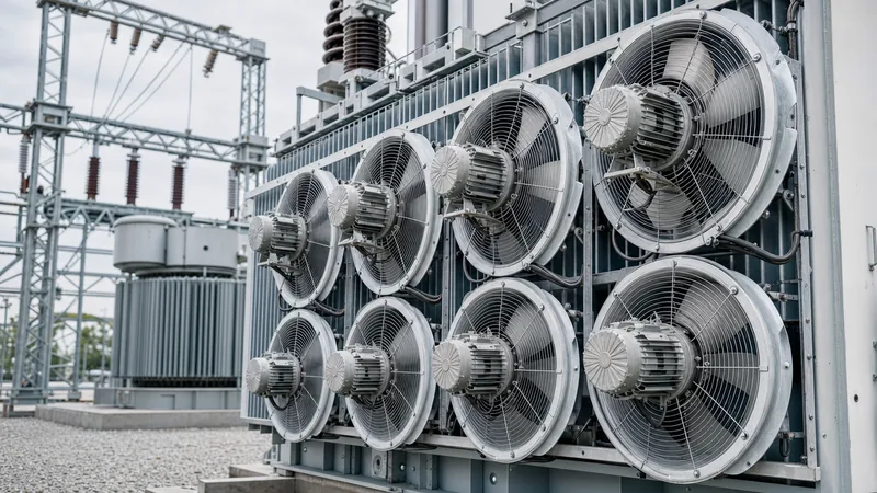
Transformer cooling fans operate as the primary active thermal mitigation mechanism on oil-filled transformer radiators, increasing convective heat rejection from radiator fins by three to four times compared to still air. When a transformer transitions from natural convection to forced air, the air velocity through the radiator flutes rises from approximately 0.3 m/s under buoyant conditions to 2.5–4.0 m/s under forced draft. For a deeper evaluation of forced convective designs, consult our ONAF transformer cooling engineering guide.
According to IEEE C57.12.00 Table 5 and IEC 60076-2 clause 5.2, power transformers carry multiple continuous ratings based on cooling mode, such as 15/20/25 MVA across natural and multi-stage forced cooling regimes. In these dual-stage or triple-stage configurations, the primary transformer fan banks engage when load losses push oil and winding temperatures toward operational thresholds. Forced air reduces the boundary-layer thermal resistance between the exterior steel radiator surface and the atmosphere. By doing so, the bottom oil temperature decreases, accelerating internal thermo-siphon circulation inside the winding cooling ducts without requiring forced-oil pumps. In OFAF configurations, fans combine with internal oil pumps to lower the top-oil-to-average-winding temperature gradient even further.
Fan Aerodynamics, Motor Types, and Control Topologies
Axial aerofoil impellers provide the optimal balance of high volumetric airflow and low static pressure required for transformer cooling banks. Unlike enclosed industrial air handling units that face high duct resistance, a transformer fan operates against the moderate backpressure of multi-plate radiator panels, typically encountering 20 to 80 Pa of static resistance across clean fin packs.
Selecting the drive architecture demands careful balance between capital expenditure, reliability, and acoustic emission:
- Aerofoil Blade Geometry: Cast aluminium or UV-stabilised reinforced composite blades reduce rotational inertia and dynamic mass unbalance. Sickle-shaped leading edges minimise turbulent vortex shedding at the blade tips, reducing high-frequency aerodynamic noise to help meet municipal substation boundary limits under IEC 60076-10.
- Electric Motor Construction: Motors must be totally enclosed air-over (TEAO) or totally enclosed fan-cooled (TEFC) designs, bearing minimum ingress protection ratings of IP55, though IP66 is standard for coastal or desert installations. Windings require Class F insulation with Class B temperature rise limits, or Class H insulation when installed in ambient environments exceeding 40°C.
- Control Topologies: Cooling systems use multi-group staging. Stage 1 fans activate at moderate load or thermal rise, while Stage 2 engages under peak loads or rapid temperature spikes. Direct online (DOL) contactors are standard, but variable frequency drives (VFD) and electronically commutated (EC) motors are increasingly specified to provide proportional speed control, soft starting, and reduced mechanical stress on mounting brackets.
Fan staging correlates directly with thermal thresholds monitored via oil and winding instruments; see our technical reference on transformer winding temperature thermal limits for trigger parameters.
Worked Sizing Calculation: Airflow and Heat Dissipation
Sizing a forced-air cooling system requires balancing the volumetric flow of air against the heat energy that radiators cannot shed through natural convection alone. The following calculation demonstrates sizing fan groups for an oil-immersed transformer undergoing an uprate from 20 MVA (ONAN) to 26.6 MVA (ONAF).
Given Parameters:
- Total transformer losses at 26.6 MVA load ($P_{total}$): 140 kW
- Losses dissipated naturally by radiator banks via ONAN ($P_{ONAN}$): 85 kW
- Incremental heat load requiring forced dissipation ($P_{fan}$): $140\text{ kW} - 85\text{ kW} = 55\text{ kW}$ ($55,000\text{ W}$)
- Maximum design ambient temperature ($T_{amb}$): 40°C
- Maximum allowable cooling air discharge temperature ($T_{out}$): 52°C ($ΔT_{air} = 12\text{ K}$)
- Density of dry air at 40°C ($ρ$): $1.127\text{ kg/m}^3$
- Specific heat capacity of air ($C_p$): $1.006\text{ kJ/(kg}·\text{K)}$
- Safety factor for fouling and uneven air distribution: 1.20
Step 1: Calculate Required Mass Flow Rate of Air
Using the thermodynamic energy balance equation:$$\dot{m} = \frac{P_{fan}}{C_p \times \Delta T_{air}} = \frac{55\text{ kW}}{1.006\text{ kJ/kg}·\text{K} \times 12\text{ K}} = 4.556\text{ kg/s}$$
Step 2: Calculate Volumetric Airflow at Ambient Conditions
$$Q = \frac{\dot{m}}{\rho} = \frac{4.556\text{ kg/s}}{1.127\text{ kg/m}^3} = 4.043\text{ m}^3\text{/s} = 14,555\text{ m}^3\text{/h}$$
Step 3: Apply Engineering Safety Factor and Select Fan Units
Applying the 1.20 safety factor to compensate for fin contamination, thermal bypass, and pressure variations:$$Q_{design} = 14,555\text{ m}^3\text{/h} \times 1.20 = 17,466\text{ m}^3\text{/h}$$
Dividing across four radiator banks, we deploy four axial transformer fans, with each unit delivering at least $4,367\text{ m}^3\text{/h}$ (2,570 CFM) at 45 Pa external static pressure. This design ensures that even during single-fan maintenance outages, the remaining units maintain safe winding operating temperatures under moderate overloads.
Engineering Comparison: Fan Motor and Blade Specifications
Selecting the correct mechanical and electrical package for substation service involves comparing construction materials against environmental severity and maintenance requirements. The table below outlines standard industrial options versus heavy-duty utility specifications.
| Engineering Parameter | Commercial Standard Fan | Heavy-Duty Substation Fan | Harsh / Coastal Specification |
|---|---|---|---|
| Impeller Material | Pressed Steel / Polypropylene | Cast Aluminium Alloy (LM6) | Marine-Grade 316 Stainless Steel |
| Motor Ingress Protection | IP54 | IP56 / IP66 | IP66 with double lip seals |
| Insulation Class | Class B (130°C) | Class F (155°C) | Class H (180°C) moisture-resistant |
| Coating Protection | Powder coated (C2) | Hot-dip galvanised / C4 paint | ISO 12944 severe marine epoxy system |
| Bearing Configuration | Sealed ball bearings (20k hrs) | Regreasable / C3 clearance (50k hrs) | Sealed-for-life synthetic grease (100k hrs) |
| Sound Pressure Level @ 2m | 72–78 dBA | 62–68 dBA (low-noise profile) | 58–64 dBA (ultra-low noise sickle) |
| Operating Temperature Range | -10°C to +40°C | -30°C to +55°C | -40°C to +65°C |
| Terminal Box Enclosure | Moulded plastic | Cast aluminium with drain plug | Cast stainless steel with breather |
Specifying the higher C4 or severe marine corrosion rating prevents rust-induced impeller imbalance, which can propagate through the radiator headers and cause oil leaks over long operational periods.
Field Installation, Maintenance, and Vibration Testing
Vibration fatigue from defective or improperly balanced fans is a primary root cause of oil leaks at radiator pipe junctions and header welds. Rigorous installation and ongoing testing prevent mechanical and thermal faults from developing into forced outages; routine checks should be incorporated into the broader substation transformer maintenance programme.
The commissioning and maintenance procedure follows these structured steps:
- Mounting Alignment and Torque Verification: Fasten the fan support frames directly to the radiator structural channels using grade 316 stainless steel or hot-dip galvanised grade 8.8 bolts. Torque all fasteners to the specified value (typically 45–50 Nm for M10 bolts) and install Belleville spring washers to resist thermal loosening.
- Airflow Direction and Shroud Clearance: Verify that the impeller rotates freely by hand, maintaining an equal radial tip clearance of 3–5 mm along the entire circumference of the venturi ring. Bump-test the motor to confirm airflow discharges directly into the radiator fins rather than pulling air outward.
- Insulation Resistance Verification: Conduct an insulation resistance test on the motor windings using a 500 V DC megohmmeter. The reading must exceed 10 MΩ at 20°C before applying line voltage.
- Operational Vibration Baseline Testing: Measure vibration velocity (mm/s RMS) on the motor bearing housings along horizontal, vertical, and axial axes during steady-state operation. Under ISO 10816-3 criteria for rigid-mounted industrial electric drives, overall vibration must not exceed 2.8 mm/s RMS (Zone A/B boundary). Readings exceeding 4.5 mm/s RMS require rebalancing the impeller or replacing worn motor bearings.
- Acoustic Profiling: Verify that combined operational noise at the substation fence does not exceed municipal noise permits, conducting measurements per IEC 60076-10 protocols.
Next steps: specifying and sourcing
Specifying the optimal cooling solution requires submitting exact radiator layout dimensions, ambient temperature extremes, target MVA uprate levels, and local acoustic thresholds. Whether you are upgrading an existing fleet or procuring factory-fitted assemblies for new plant, our engineering team can model heat dissipation profiles to match your operating parameters. Explore our high-efficiency substation power transformers and robust oil-immersed distribution units to evaluate integrated cooling configurations. For project tenders, component replacement lists, or custom radiator fan banks, submit your single-line diagrams and thermal schedules via our transformer quotation page.
Frequently asked questions
What is the primary function of a transformer fan?
A transformer fan forces air across external radiator banks to accelerate convective heat dissipation. This reduces top-oil and winding temperatures, allowing the transformer to carry continuous loads up to 33% above its natural cooling rating.
What is the difference between ONAN and ONAF cooling?
ONAN relies on natural oil thermo-siphoning and natural atmospheric air draft to dissipate heat. ONAF retains natural internal oil circulation but uses forced draft from external fans across the radiators to increase cooling capacity.
How are transformer cooling fans controlled?
Transformer cooling fans are automatically controlled by winding temperature indicators (WTI) or top-oil temperature indicators (OTI) using microswitches. Alternatively, modern digital transformer protection relays trigger fan contactors or variable frequency drives based on real-time thermal models.
What IP rating is recommended for an outdoor transformer fan?
An outdoor transformer fan should have an ingress protection rating of at least IP55 to safeguard against wind-blown dust and rain. Severe environments, such as marine substations or desert sites, typically require IP56 or IP66 enclosures.
What causes excessive vibration in transformer cooling fans?
Excessive vibration is typically caused by aerodynamic unbalance from dirt accumulation, loose blade hardware, bent impellers, or worn motor bearings. Vibration levels should remain below 2.8 mm/s RMS to prevent fatigue cracks in adjacent radiator pipework.
Can transformer fans be retrofitted to an existing ONAN transformer?
Yes, transformer fans can be retrofitted to radiators if the internal winding cooling ducts and electrical clearances can accommodate the uprated thermal throughput. Radiator brackets, auxiliary power supplies, and control circuit wiring must be sized accordingly.
Tags: transformer fan transformer cooling fans ONAF cooling transformer thermal design substation cooling


