Key takeaways
- ONAF cooling increases transformer power capacity by 25% to 33% over its base ONAN rating by using external fans to accelerate radiator convective heat dissipation.
- Under IEC 60076-2 and IEEE C57.12.00 standards, the ONAF designation defines natural thermosiphon internal dielectric liquid circulation paired with forced external air flow across cooling surfaces.
- Ester-filled transformers designated as KNAN or KNAF require larger radiator surfaces or higher fan velocities due to the higher kinematic viscosity of synthetic and natural esters relative to mineral oil.
- A standard dual-stage ONAF control system triggers fan stage one at a winding temperature indicator threshold of 65°C to 75°C and stage two between 75°C and 85°C to preserve paper insulation life.
- Factory temperature rise testing per IEC 60076-2 clause 7 requires steady-state short-circuit injection until top-oil temperature change is less than 1 K per hour before taking shut-down hot resistance measurements.
Quick answer: In an onaf transformer cooling oil natural air forced design, heat generated inside the core and windings transfers to the insulating oil via natural convection (thermosiphon action), while external motorized fans blow ambient air across the radiator banks to accelerate atmospheric dissipation. This dual-mode cooling regime allows a power transformer to carry 25% to 33% more electrical load during peak demand periods without exceeding standardized winding temperature rise limits.
Substation and industrial plant engineers frequently specify dual-rated transformers capable of operating in both base passive cooling and boosted forced-air modes. Liquid-immersed power units generate internal I²R copper losses and magnetic core losses that degrade solid cellulose insulation if operating temperatures breach international limits. By incorporating radiator fan arrays, asset owners maintain low capital expenditure while gaining the operational flexibility to handle intermittent loading peaks, renewable generation surges, and elevated summer ambient temperatures.
Understanding how an onaf transformer cooling oil natural air forced arrangement functions requires examining fluid thermodynamics, radiator skid layout, acoustic noise mitigation, and automatic fan staging. Selecting the correct power transformer cooling configuration ensures the asset reliably delivers its designed 30- to 40-year service life without accelerated dielectric ageing.
ONAF Cooling Meaning: Oil Natural Air Forced Transformer Fundamentals
The onaf cooling meaning oil natural air forced transformer definition describes a hybrid cooling method where internal liquid moves by buoyant thermal forces alone, while external air is propelled mechanically across heat exchanger surfaces.
Internally, heat produced within the high-voltage (HV) and low-voltage (LV) conductor coils transfers directly into the surrounding dielectric fluid through thermal conduction. Because warm liquid exhibits lower density than cooler liquid, a buoyant vertical plume forms along the winding ducts. This buoyancy-driven flow pushes the heated liquid into the transformer tank top header, directing it outward through upper isolation valves into external pressed-steel radiator panels or tubular radiator banks.
As the liquid flows downward through the radiator fins, it cools, increases in density, and settles toward the bottom header before re-entering the main tank base. In an onaf transformer cooling oil natural air forced design, this internal hydraulic circuit relies strictly on the thermosiphon effect without mechanical oil pumps. When ambient cooling demand increases, mounted radiator fans activate to direct high-velocity horizontal or vertical airflow across the external radiator elements. This forced convective airflow increases the overall heat transfer coefficient (U-value) from approximately 12–15 W/(m²·K) in passive conditions to 30–45 W/(m²·K), enabling far greater heat extraction per square metre of radiator surface.
Transformer Cooling Class Designations Under IEC and IEEE Standards
Cooling class terminology is defined by international standards bodies through a four-letter code that specifies the internal cooling medium, its circulation mechanism, the external cooling medium, and its circulation mechanism.
According to IEC 60076-2 clause 4 and IEEE C57.12.00 Table 1, liquid-immersed transformers adopt four-letter designations to prevent operational ambiguity during procurement and factory acceptance testing:
- First letter (Internal medium): 'O' denotes mineral oil or synthetic hydrocarbons with fire point ≤ 300°C; 'K' denotes insulating liquids with fire point > 300°C (such as natural or synthetic esters); 'L' denotes insulating liquids with no measurable fire point.
- Second letter (Internal circulation): 'N' indicates natural thermosiphon circulation through cooling equipment and internal windings; 'F' indicates forced liquid circulation through cooling equipment with natural flow inside windings; 'D' indicates forced, directed circulation directly channeled into winding ducts.
- Third letter (External cooling medium): 'A' indicates ambient atmospheric air; 'W' denotes water.
- Fourth letter (External circulation): 'N' indicates natural convective air flow; 'F' denotes forced mechanical draft driven by fans.
Under these definitions, a unit with an ONAN/ONAF rating operates as an onan transformer under light or moderate loads without auxiliaries, then transitions to an onaf transformer cooling oil natural air forced state when the cooling fans energise. Historically, North American IEEE standards utilized terms such as OA (Oil Natural/Air Natural), FA (Forced Air), and OA/FA/FOA. Modern specification documents globally have harmonized around the four-letter IEC cooling class standard to eliminate confusion during cross-border equipment procurement.
ONAN Transformer vs ONAF: Operating Mechanisms and Heat Transfer Dynamics
The core distinction between an onan transformer and an onaf transformer cooling oil natural air forced system lies in the external boundary layer air velocity and the resulting convective thermal resistance.
In a standard ONAN configuration, atmospheric air adjacent to the outer radiator steel warms, drops in density, and rises passively by natural convection. This process creates a laminar thermal boundary layer across the cooling fins that limits the air-side heat dissipation rate. Under these passive conditions, dissipation relies heavily on ambient wind conditions, radiative emission from painted surfaces, and broad fin pitch to prevent stagnant air pockets between adjacent radiator elements.
When external cooling fans turn on, the cooling regime switches to forced air convection. The high-velocity turbulent air stream disrupts the stagnant thermal boundary layer clinging to the radiator surfaces, significantly reducing the thermal resistance between the exterior metal and the surrounding atmosphere. The heat flow equation demonstrates this advantage:
Q = U × A × ΔTm
Where Q is rejected thermal power (W), U is the overall heat transfer coefficient (W/m²·K), A is radiator surface area (m²), and ΔTm is the logarithmic mean temperature difference between the dielectric liquid and ambient air. Because forced mechanical airflow raises U by a factor of 2.5 to 3.0, an operator can extract substantially more heat without expanding the physical footprint of the transformer tank or the total oil volume.
Synthetic and Natural Esters: KNAN Transformer and KNAF Performance
A knan transformer utilizes a less flammable K-class dielectric fluid, which alters convective cooling dynamics because of its physical viscosity profile compared to standard mineral oil.
Ester liquids, derived from natural vegetable seeds or synthetic organic acids, provide elevated fire safety (fire points exceeding 300°C per ISO 2592) and rapid biodegradability. However, their kinematic viscosity at typical operating temperatures (40°C to 70°C) is roughly two to three times greater than that of standard naphthenic mineral oil. In natural thermosiphon flow, higher viscosity creates greater internal flow resistance through narrow core and winding oil channels.
| Cooling Fluid & Class | Kinematic Viscosity at 40°C (mm²/s) | Fire Point (°C) | Typical Radiator Surface Margin vs Mineral Oil | Thermosiphon Velocity Profile |
|---|---|---|---|---|
| Mineral Oil (ONAN/ONAF) | 9.0 – 11.0 | 140 – 170 | Baseline (0%) | Standard natural loop velocity |
| Synthetic Ester (KNAN/KNAF) | 28.0 – 30.0 | > 300 | +10% to +15% | Moderately dampened thermosiphon |
| Natural Ester (KNAN/KNAF) | 32.0 – 37.0 | > 315 | +15% to +25% | Lowest natural loop velocity |
Consequently, an asset transitioning from KNAN to KNAF requires detailed thermal-hydraulic engineering. The manufacturer must increase the vertical cross-sectional area of internal oil passages, optimize radiator header heights to maximize driving head pressure, or employ larger-diameter external radiator headers to compensate for fluid drag. Failing to account for ester viscosity during radiator skid sizing leads to elevated winding hotspot temperatures under forced-air peak ratings.
Thermal Up-Rating and Fan Control: Calculating the ONAF Boost Ratio
A dual-rated transformer sizing strategy calculates the permissible ONAF MVA rating based on total internal losses, cooling surface characteristics, and thermal limits prescribed in IEC 60076-2 Table 1.
To evaluate how an onaf transformer cooling oil natural air forced arrangement manages heat dissipation, consider a typical step-down substation unit designed for utility or industrial service. For further sizing methodologies, engineers should reference the comprehensive transformer sizing calculator guide when aligning core capacity with cyclic duty cycles.
Worked Engineering Calculation: Thermal Rating and Temperature Rise- Rated Design Parameters:
- ONAN Base Rating (SONAN): 20.0 MVA
- Target ONAF Rating (SONAF): 25.0 MVA (25% thermal up-rate)
- No-Load Core Losses (P0): 16.5 kW (constant)
- Load Losses at ONAN Rating (Pk_ONAN): 82.0 kW
- Rated Frequency: 50/60 Hz; Ambient Design Temperature: 40°C maximum
- Total Losses at ONAF Continuous Loading:
Because load losses scale with the square of the current ratio (and thus MVA ratio):
Pk_ONAF = Pk_ONAN × (SONAF / SONAN)²
Pk_ONAF = 82.0 kW × (25.0 / 20.0)² = 82.0 × 1.5625 = 128.1 kW
Ptotal_ONAF = P0 + Pk_ONAF = 16.5 kW + 128.1 kW = 144.6 kW - Thermal Equilibrium Evaluation:
Under ONAN conditions, total dissipated loss is 16.5 + 82.0 = 98.5 kW, yielding an oil temperature rise (Δθoil) of 50 K above 40°C ambient (90°C top oil).
When forced-air fans operate, external heat transfer capacity increases by a factor of 1.65 across the radiator cluster.
Δθoil_ONAF = Δθoil_ONAN × (Ptotal_ONAF / Ptotal_ONAN)x × (1 / Cooling_Factor)
Assuming oil exponent x = 0.8 per IEC 60076-7:
Δθoil_ONAF = 50 × (144.6 / 98.5)0.8 × (1 / 1.65)0.8 = 50 × 1.356 × 0.672 = 45.6 K
Because 45.6 K remains well below the IEC 60076-2 top-oil limit of 60 K (or 55 K for non-conservator sealed units), the insulation is protected from accelerated thermal degradation.
Auxiliary fan control cabinets govern this transition automatically using contact outputs from the Top Oil Temperature Indicator (OTI) and Winding Temperature Indicator (WTI). Typically, Fan Stage 1 activates at a WTI setpoint of 65°C to 70°C, and Fan Stage 2 energises if winding temperatures reach 75°C to 80°C. Deactivation occurs with a 10 K downward hysteresis to prevent frequent contactor cycling.
Cooler Transformer Radiator Bank and Fan Skid Engineering
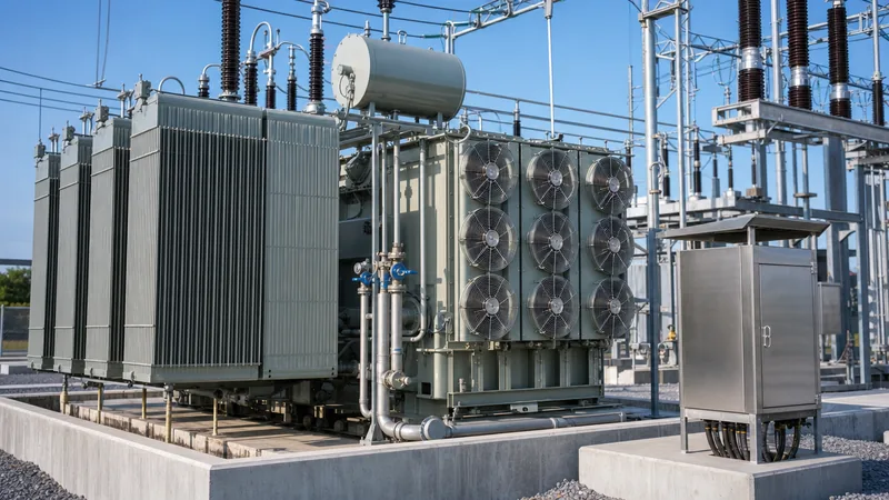
A cooler transformer radiator assembly consists of pressed carbon-steel fluted panels, header manifolds, structural bracing, and aerodynamically shaped fan cowls arranged for continuous outdoor duty.
Designing radiator banks for transformers with air forced cooling involves several mechanical, acoustic, and electrical layout criteria:
- Radiator Bank Configurations: Radiators can be mounted directly on the transformer tank walls using butterfly isolating valves or assembled as a freestanding, skid-mounted radiator bank connected by flexible stainless-steel bellows. Detachable panel designs allow individual radiator sections to be isolated, drained, and removed for maintenance without taking the entire unit out of service.
- Airflow Orientation: Fan assemblies are installed in either a bottom-blown arrangement (directing air upward between vertical radiator elements) or a side-blown arrangement (directing air horizontally across the flutes). Bottom-blown layouts provide higher air velocity inside deep fin packs, while side-blown fans offer easier ground-level access for maintenance.
- Acoustic Noise Control: Standard industrial cooling fans generate significant broadband aerodynamic and motor noise (typically 65 to 78 dBA per fan at 2 metres). In residential substations or commercial installations, engineers must specify low-noise, sickle-blade axial fans or variable-speed DC/EC (electronically commutated) motor drives to meet boundary acoustic criteria without compromising airflow.
- Ingress Protection: Fan drive motors must carry IP55 or IP56 ingress ratings per IEC 60529, with Class F insulation and sealed-for-life stainless steel bearings to prevent moisture contamination and bearing seizure over decades of exposure.
For installations involving on-load tap changers, the cooling layout must also prevent tap-changer oil compartments from receiving hot air exhaust from main radiator skids, as detailed in our guide on load tap changer engineering.
Testing and Verification: Heat Run Test Procedures
Factory heat run verification under IEC 60076-2 clause 7 confirms that actual temperature rises under both ONAN and ONAF cooling modes match design guarantees before equipment leaves the factory.
The standard temperature rise test is conducted inside the manufacturer's high-voltage laboratory using the short-circuit method. The transformer's LV terminals are securely short-circuited with rated copper busbars, and a test source applies voltage to the HV windings sufficient to circulate total losses (no-load core losses plus full load losses multiplied by the reference temperature correction factor).
- Total Loss Injection: The unit operates under continuous short-circuit current with cooling fans running until thermal equilibrium is attained. Equilibrium is established when the rate of top-oil temperature rise does not exceed 1 K per hour over a consecutive four-hour measurement window.
- Rated Current Reduction: Once top-oil rise is verified, the input test current is immediately reduced to 100% rated current for one hour. This stabilises the average winding-to-liquid temperature gradient.
- Shutdown Resistance Measurement: The main power source is disconnected, terminal shorting bars are removed, and sensitive micro-ohmmeters record winding DC resistance over time. Using extrapolation curves based on the cooling schedule described in standard procedures—such as those outlined in our transformer testing guide—the average winding temperature rise at the instant of power shutdown is precisely calculated.
Oil samples taken before and after the heat run test undergo dissolved gas analysis (DGA) to ensure no localized thermal hotspots exceeding 300°C emerged during maximum ONAF loading.
Engineering Specification and RFQ Checklist for ONAF Transformers
An accurate procurement specification must detail environmental design limits, auxiliary electrical supply voltages, fan redundancy criteria, and control instrumentation to ensure reliable substation performance.
| Technical Parameter | Recommended Engineering Requirement | Governing Standard / Reference |
|---|---|---|
| Cooling Designation | ONAN / ONAF (or KNAN / KNAF if ester filled) | IEC 60076-2 Clause 4 / IEEE C57.12.00 |
| Winding Temperature Rise Limit | ≤ 65 K (Mineral Oil) / ≤ 70 K (Thermal Upgraded Paper) | IEC 60076-2 Table 1 |
| Top-Oil Temperature Rise Limit | ≤ 60 K (Conservator) / ≤ 55 K (Sealed Tank) | IEC 60076-2 Table 1 |
| Fan Redundancy Factor | N+1 design (100% capacity with any one fan out of service) | User / Utility Project Specification |
| Fan Motor Supply & Protection | 400V/230V, 3-Phase, IP55, individual thermal overloads | IEC 60034-1 / IEC 60529 |
| Corrosion Protection | Hot-dip galvanised radiators or marine-grade epoxy paint | ISO 12944-5 |
| Control Logic & Interface | Auto/Manual switch, dual-stage WTI contacts, SCADA alarms | IEC 61850 Substation Integration |
To avoid operational difficulties down the road, verify that the radiator steel wall thickness is at least 1.2 mm (1.5 mm in coastal or chemically aggressive settings). Integrating digital monitoring with the plant SCADA network provides continuous visibility over fan motor current draw, helping maintenance crews detect worn fan bearings before thermal derating occurs. Combining these thermal safeguards with adequate transformer protection architectures ensures the unit remains protected under abnormal operating events.
Maintenance and Lifecycle Management of Forced-Air Radiator Systems
Routine maintenance of forced-air cooling systems focuses on cleaning radiator surfaces, checking fan motor condition, and testing automated thermostat control loops.
Over months of outdoor operation, debris such as leaves, industrial dust, and pollen collects between adjacent radiator fins, creating an insulating thermal barrier that diminishes airflow. Maintenance teams should clean radiator banks during scheduled outages using low-pressure washdowns or compressed air sprays directed parallel to the fin orientation to avoid bending delicate metal flutes. Technicians should also review oil quality periodically, as particulate accumulation and oxidation degrade natural thermosiphon efficiency, making the procedures covered in our transformer oil purification guide critical to long-term performance.
Auxiliary motor circuits also require annual electrical inspections:
- Measure motor winding insulation resistance at 500 V DC to verify levels exceed 10 MΩ.
- Inspect fan impeller fasteners for correct torque and verify blade clearances inside cowlings.
- Manually initiate test runs for all fan stages from the Marshalling Kiosk to verify auxiliary contactors engage cleanly and signal alarms register accurately on substation SCADA systems.
- Check vibration levels on fan motor cowlings to catch early bearing mechanical failure before impellers contact fan housing guards.
Next steps: specifying and sourcing
Specifying an onaf transformer cooling oil natural air forced system requires aligning ambient environmental conditions, peak capacity targets, and acoustic constraints into a unified technical schedule. Whether upgrading an existing transmission substation or procuring new medium-power generation equipment, our engineering design team reviews loss parameters, elevation derating factors, and fan staging architectures to deliver compliant equipment built to IEC 60076, IEEE C57, and ISO quality management standards.
Review our heavy-duty oil-immersed transformer range or examine our complete power transformer engineering solutions. For detailed sizing estimates, project reviews, or formal tender pricing, reach out to our application engineers via our contact page or submit full project single-line drawings directly through our online quote request form.
Frequently asked questions
What does ONAF stand for in transformer cooling?
ONAF stands for Oil Natural Air Forced cooling. In this system, insulating oil circulates inside the transformer tank and radiators solely by natural buoyancy (thermosiphon effect), while external electric fans force ambient air across the radiator banks to enhance external cooling capacity.
What is the difference between ONAN and ONAF cooling?
An ONAN transformer relies entirely on natural thermosiphon liquid circulation and natural atmospheric air convection over its radiators. An ONAF transformer utilizes external motorized cooling fans to blow air actively across the radiator surfaces, typically providing a 25% to 33% increase in usable power capacity over its base ONAN rating.
Can an ONAF transformer run continuously without its cooling fans?
Yes, an ONAF transformer can run continuously without fans, but it must be de-rated to its base ONAN capacity (typically 70% to 80% of its full ONAF rating). Operating above the ONAN limit without cooling fans causes rapid oil overheating and degrades solid cellulose insulation.
What is the meaning of a KNAN transformer cooling class?
A KNAN cooling class designates a transformer filled with an insulating liquid possessing a fire point greater than 300°C (such as natural or synthetic ester), circulating via natural convection ('N'), with natural external air convection ('AN'). When cooling fans are added, it becomes a KNAF system.
At what temperature do transformer cooling fans typically start?
Transformer cooling fans are typically controlled by winding temperature indicators (WTI) and top-oil temperature indicators (OTI). Stage 1 fans typically activate when the winding temperature reaches 65°C to 75°C, while Stage 2 fans energise between 75°C and 85°C, switching off once temperatures drop roughly 10°C below these setpoints.
What are the common fan failure modes on ONAF transformers?
Common fan failure modes include moisture ingress causing motor winding insulation breakdown, bearing seizure from degradation of factory grease, physical damage from windblown debris, and failed magnetic contactors or thermal overload relays inside the auxiliary control cabinet.
Tags: onaf transformer cooling oil natural air forced cooling class onaf cooling meaning oil natural air forced transformer onan transformer knan transformer cooler transformer


