Key takeaways
- A transformer ttr test verifies the physical turn count between primary and secondary windings to detect internal short circuits, open turns, and incorrect tap connections.
- Both IEC 60076-1 clause 10.3 and IEEE C57.12.00 clause 9.1 mandate a measured ratio tolerance within plus or minus 0.5% of the calculated nameplate turns ratio.
- Three-phase vector groups (such as Dyn11 or Ynd1) introduce a square-root-of-three factor and phase displacement that test equipment must resolve to determine the true individual phase ratio.
- Phase angle deviation during transformer turns ratio testing should not exceed 0.5 degrees on standard power units, with larger shifts indicating core saturation or winding distortion.
- Routine ratio testing across every tap position on de-energised tap changers (DETC) and on-load tap changers (OLTC) prevents catastrophic phase-to-phase faults prior to site energisation.
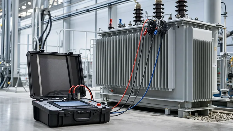
Quick answer: A transformer ttr test (transformer turns ratio test) measures the exact ratio of primary to secondary winding turns to confirm voltage transformation accuracy, winding integrity, and tap-changer functionality. International standards enforce an acceptance tolerance of within ±0.5% of the declared nameplate ratio on all tap positions.
During manufacturing, factory acceptance testing (FAT), and on-site commissioning, verifying transformer turns ratio testing is a non-negotiable quality gate. Any discrepancy beyond standard limits points directly to severe internal defects: short-circuited turns, axial winding displacement after transport, open circuits, or incorrect tap-changer selector cabling. As detailed in our guide on power transformer testing, ratio measurements form the foundational baseline for all subsequent magnetic and dielectric evaluations.
Working Principle of Transformer Turns Ratio Testing
Tags: transformer ttr test transformer turns ratio testing transformer testing electrical acceptance testing IEC 60076-1


