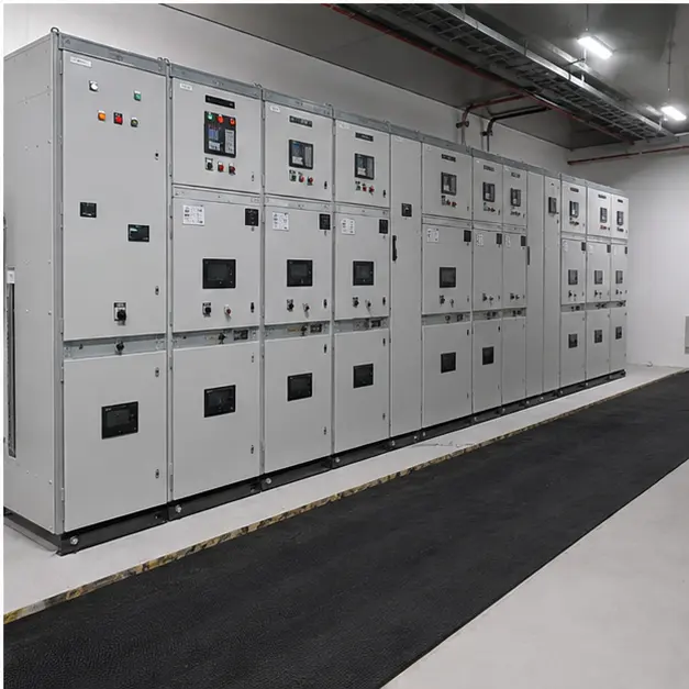
At a glance
| Country | United Arab Emirates |
|---|---|
| Application | Large commercial building complex |
| System | 11 kV metal-clad switchgear lineup with low-voltage distribution |
| Voltage | 11 kV incoming / low-voltage distribution |
| Frequency | 50 Hz |
| Standards basis | IEC 62271-200 (AC metal-enclosed switchgear), IEC 62271-1 (common specifications), IEC 61439-1/-2 (LV assemblies), IEC 60529 (IP), IEC 60068-2 and ISO 12944/ISO 9223 (climatic and corrosion classification), IEC 61850 or IEC 60870-5 for supervisory interface |
| Visual status | Representative project visualization |
The engineering problem
An 11 kV intake serving a large commercial complex in the UAE is not a difficult switching problem. It is a thermal and corrosion problem wrapped around a switching problem, and it is that combination which sets the specification.
Design ambient is the first driver. Summer shade temperatures reaching 50 °C leave almost no headroom against the 40 °C reference ambient in IEC 62271-1 and IEC 61439-1. Rated continuous current has to be derated, or the busbar cross-section increased, or the switchroom actively cooled — usually a mixture of all three. A lineup specified on nameplate current alone will run its joints hot, and joint temperature is what ages the insulation and the silver plating.
Second, the coastal Gulf environment is corrosive in a way that inland desert is not. Airborne chloride combined with high absolute humidity and long overnight dew periods gives a high atmospheric corrosivity category. Sheet steel treatment, plating on current-carrying contacts and the sealing of any enclosure that breathes all follow from that classification rather than from a default finish.
Third, the practice for buildings of this class is an indoor MV room: switchgear in a dedicated, environmentally controlled, restricted-access space, with defined escape routes, arc-venting provision and a maintenance philosophy built on withdrawable circuit breakers. That makes room geometry a design input — panel depth, rear access width, cable trench depth and the route for arc-fault pressure relief have to be agreed before the lineup is manufactured, not discovered on site.
Finally, tenant supply continuity in a commercial complex favours a sectionalised busbar with defined interlocking, so that a fault or maintenance outage on one section does not take the whole building down.
System configuration
| Item | Description | Specification notes |
|---|---|---|
| MV switchgear lineup | 11 kV indoor metal-clad panels, incoming, bus-section and outgoing feeders | IEC 62271-200; compartmentalised construction with loss-of-service continuity category and internal arc classification agreed for the room layout and personnel access sides |
| Circuit breakers | Withdrawable vacuum circuit breakers on incomers, bus-section and feeders | Rated current derated for the design ambient; short-circuit breaking and short-time withstand set by the utility fault level and clearing time |
| Busbar system | Main and earthing busbars, sectionalised with a bus-section device | Cross-section sized on derated continuous current at site ambient, not the 40 °C reference; plated joints, torque-controlled and marked |
| Protection and metering | Overcurrent, earth-fault, and where required directional or differential protection, with tariff and check metering | CT and VT classes matched to protection accuracy and metering requirements; grading coordinated with the utility upstream device |
| Interlocking and safety | Mechanical and electrical interlocks, earthing switch, shutters, voltage presence indication and cable-compartment access control | Interlock logic defined so no sequence permits access to an unearthed compartment; capacitive voltage indication to IEC 62271-206 |
| LV distribution | Low-voltage main assembly and outgoing distribution to building services | IEC 61439-1/-2; form of separation and short-circuit withstand set by the transformer rating, cable impedance and maintenance policy |
| Cable interface | Rear or bottom cable compartments, trench entry, gland plates and screen bonding | Bending radius, trench depth and pulling tensions checked against the cable type; non-magnetic gland plates where single-core cables pass |
| Room services | Air conditioning or forced ventilation, anti-condensation heating, arc pressure relief route | Cooling sized on total lineup and transformer losses at the design ambient; humidity control specified against coastal dew conditions |
| Monitoring and communication | Relay and metering data concentrated to a gateway for the building management or utility SCADA system | IEC 61850, IEC 60870-5-104 or Modbus TCP; alarm and status points list agreed at design stage |
Installation sequence
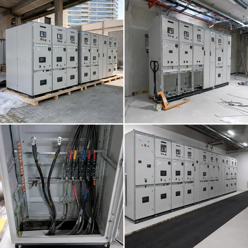
Overview
The contact sheet sets out the four stages of an installation of this type: delivery of the panels, positioning and alignment inside the electrical room, rear cable termination and earthing, and the completed lineup ready for energisation. The order is fixed by access. The room must be structurally complete, dry, dust-free and environmentally controlled before panels enter, because a metal-clad lineup is a clean-room item once the shipping covers come off. Panels are aligned and coupled before any cable is terminated, since alignment moves busbar joints. Functional and primary injection testing is done while the compartments are still open, and the room is handed over only after the cooling and pressure-relief provisions are proved.
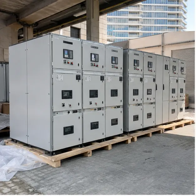
Delivery
Panels arrive shrink-wrapped or crated, with desiccant, and the first check is whether they arrived dry. In a Gulf climate the risk between the container and the switchroom is condensation, not rain: a cold-shipped panel opened in humid outdoor air will condense on internal insulation. Panels are moved into a conditioned space before unwrapping wherever practical. Receiving inspection covers transit damage, shock-indicator status, panel identity against the lineup drawing, breaker and truck condition, and the presence of shipping braces. Handling uses the designated base channels or lifting lugs — a metal-clad panel is top-heavy with the breaker in place, so breakers are normally withdrawn and moved separately before any lifting or skating.
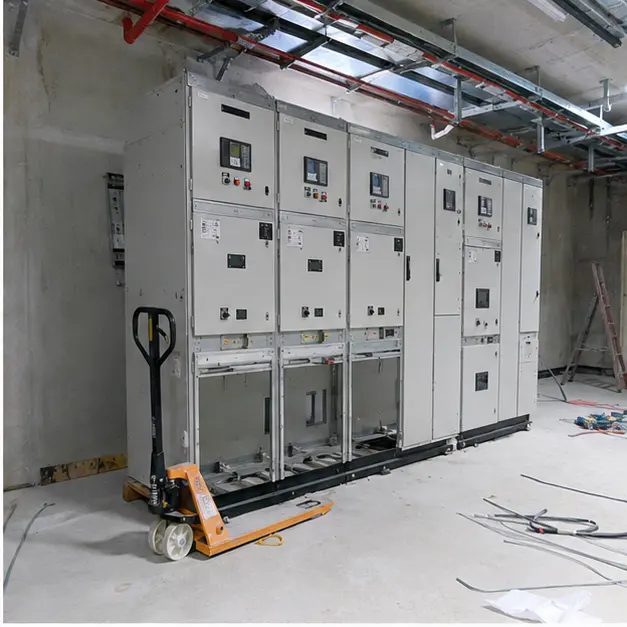
Positioning
Positioning is a precision activity, not a placement. The floor or channel base is surveyed for level and flatness across the full run before the first panel is set, because cumulative error appears as a busbar joint that will not close square. Panels are set to the datum line, shimmed where necessary, bolted to the base steel and coupled to their neighbours, and only then are the interconnecting busbar links fitted and torqued. Squareness matters mechanically as well as electrically: withdrawable trucks must rack in and out freely on every cubicle, and shutters and interlocks must operate without binding. Panel-to-panel earth continuity is bonded across every joint as the run is built up.
Cable work
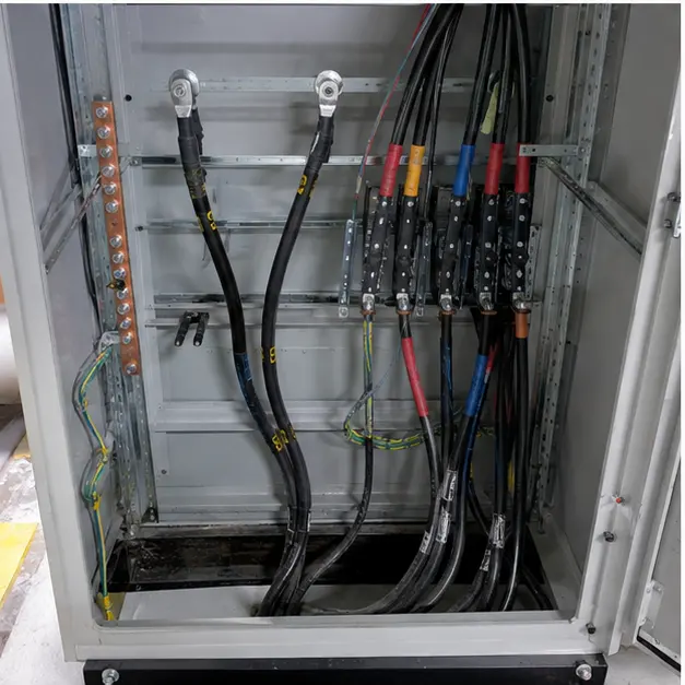
MV terminations in the rear compartments are the highest-risk workmanship on the installation. Screen cut-back length, semiconducting layer removal, surface cleanliness and correct stress-cone seating decide whether a termination lives for decades or fails within months, and in coastal humidity the work is completed in one controlled session rather than left part-made overnight. Bending radius is respected into the compartment; cables are cleated so their weight and any short-circuit force is not carried by the terminal. Screens are bonded to the earth bar with a conductor sized for the prospective earth-fault current and clearing time. Gland plates are sealed to maintain the compartment rating, and all terminal bolts are torqued to value and paint-marked.
Completed configuration
Before energisation the lineup is proved as a chain rather than as parts. Insulation resistance and, where specified, power-frequency withstand are recorded; contact resistance across each breaker pole and each busbar joint is measured against value, since a high-resistance joint is the origin of most thermal failures; interlock and racking sequences are proved by operation; protection is tested end-to-end by primary or secondary injection so that relay, CT circuit, trip coil and breaker are proved together. Earth continuity is confirmed from every panel and door back to the main earth bar. Room cooling, anti-condensation heating and pressure-relief routing are functionally checked, and the arrangement shown is then labelled, single-line diagram displayed, and energised in a staged sequence.
Specification options
For a comparable enquiry, MARS can configure the lineup around the rated voltage and insulation level, busbar continuous current, short-circuit and short-time withstand rating, and the loss-of-service continuity and internal arc classification appropriate to the room. Panels can be supplied as air-insulated metal-clad with withdrawable vacuum breakers, or as SF6 or solid-insulated ring main units where footprint governs. Protection can range from self-powered overcurrent and earth-fault relays to full numerical protection with directional, differential and arc-flash detection, with CT and VT classes to suit tariff metering. Enclosure treatment, plating and IP rating can be specified against the coastal corrosivity category. Transformers can be cast-resin dry-type for indoor fire load or oil-immersed with containment, and LV assemblies supplied in the required form of separation. Communication can be IEC 61850, IEC 60870-5-104 or Modbus TCP.
What we need to quote a comparable system
Send as many of the following as you have. Missing items are not a problem — we will ask.
- Single-line diagram showing intake, bus arrangement, sectionalising and outgoing feeders
- Incoming voltage, insulation level and the utility connection agreement or specification
- Required busbar continuous current and the outgoing feeder schedule with loads
- System fault level at the point of connection, required short-time withstand and clearing time
- Loss-of-service continuity category and internal arc classification, with the accessible sides
- Protection philosophy, relay preferences, and any existing grading study or settings
- Metering requirement — tariff, check or sub-metering — and the CT/VT classes it implies
- Design ambient temperature range, humidity, and whether the room is air-conditioned or ventilated
- Coastal corrosivity classification, required panel finish, plating and IP rating
- Room dimensions, ceiling height, access route, trench depth and cable entry direction
- Communication protocol, points list and the building management or SCADA interface
- Transformer requirement, LV assembly form of separation, and delivery terms