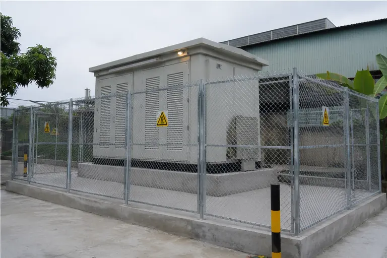
At a glance
| Country | Vietnam |
|---|---|
| Application | Industrial manufacturing facility |
| System | 22 kV/0.4 kV compact prefabricated substation |
| Voltage | 22 kV incoming / 0.4 kV outgoing |
| Frequency | 50 Hz |
| Standards basis | IEC 62271-202 (prefabricated HV/LV substation), IEC 60076 series (transformer), IEC 62271-200 (MV switchgear), IEC 61439-1/-2 (LV assembly), IEC 60529 (IP) |
| Visual status | Representative project visualization |
The engineering problem
Vietnamese industrial supply is typically taken at 22 kV, and a manufacturing plant needs that stepped down to 0.4 kV as close to the load centre as the site allows. Distance costs money twice: in LV copper, and in voltage drop that erodes motor starting performance.
A compact prefabricated substation answers this by putting MV switching, transformation and LV distribution inside one factory-built enclosure that can be placed in the yard, near the production block, rather than inside a purpose-built masonry room. The building work reduces to a foundation and a trench.
The climate sets the harder constraints. Northern and southern Vietnam both run high humidity year-round, with a long wet season and frequent lightning. Condensation inside an outdoor MV enclosure is a genuine insulation risk, so ventilation, anti-condensation heating and drainage matter as much as the switchgear rating. Coastal and delta sites add chloride loading, which drives the coating class rather than the electrical design.
Thermally, a sealed enclosure holds the transformer’s losses. Enclosure classification under IEC 62271-202 exists precisely because a transformer that is fine in open air can exceed its temperature-rise limit inside a box. A system of this type is sized on the enclosure class, not on the transformer nameplate alone.
System configuration
| Item | Description | Specification notes |
|---|---|---|
| Enclosure | Factory-built compact substation housing, outdoor rated | Sheet steel or GRP; IP and corrosion class selected for the site; enclosure class per IEC 62271-202 governs permitted transformer loading |
| MV switching | Ring main unit or MV switchgear compartment for the 22 kV incomer | SF6 or solid-insulated RMU, or air-insulated metal-clad panel where extension is expected; internal arc classification specified for the room layout |
| Transformer | 22 kV/0.4 kV distribution transformer | Oil-immersed (S11/S13 type) or cast-resin dry-type (SCB series) depending on fire strategy and enclosure ventilation |
| LV distribution | Low-voltage main board and outgoing ways | IEC 61439-1/-2 assembly; form of separation and short-circuit withstand set by the plant's fault level and maintenance policy |
| Protection | MV fuse or relay protection, LV main and feeder breakers | Grading between MV, transformer and LV stages so a feeder fault does not trip the incomer |
| Thermal management | Natural or forced ventilation, louvres with insect and rain screens, anti-condensation heaters | Ventilation path sized for the transformer's total losses at the design ambient |
| Earthing | Enclosure bonding, transformer neutral earthing, external earth electrode connection | Conductor sized for prospective earth-fault current and clearing time; bonding independent of paint or hinges |
| Cable interface | MV cable entry, LV outgoing entries, trench and gland plates | Non-magnetic gland plates for single-core LV cables; entry positions set so minimum bending radius is respected |
| Monitoring | Temperature indication, door and alarm contacts, optional communication gateway | Modbus RTU/TCP, IEC 61850 or DNP3 where an arrangement of this type must report to a plant SCADA |
Installation sequence
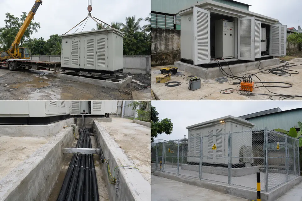
Overview
The contact sheet sets out the four working stages of an installation of this type: delivery, placement and testing, cable and earthing work, and the completed installation. Reading them together shows why the order is fixed. Foundation and earth electrode work has to be finished and proved before the enclosure lands on it, because the electrode connection point is usually inaccessible afterwards. Cable pulling follows placement so that final route lengths are measured rather than estimated. Testing that would require the enclosure to be opened is completed before the site is fenced and handed over. Each stage constrains the next, which is why sequencing is planned at design stage rather than on site.
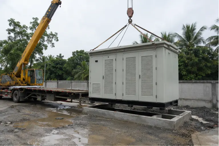
Delivery
A compact substation of this type is transported as a single integrated unit and is at its most vulnerable in transit. It is a tall, relatively light body with the transformer mass concentrated low and to one side, so lashing has to restrain lateral movement rather than just hold the unit down. On arrival the enclosure is checked for transport damage, door and louvre alignment, and — for an oil-immersed transformer inside — oil level and any sign of leakage at gasketed joints. Impact recorders, where fitted, are read before the unit is accepted. Lifting is by the designated points only, with spreader beams sized so the slings do not bear on the enclosure walls.
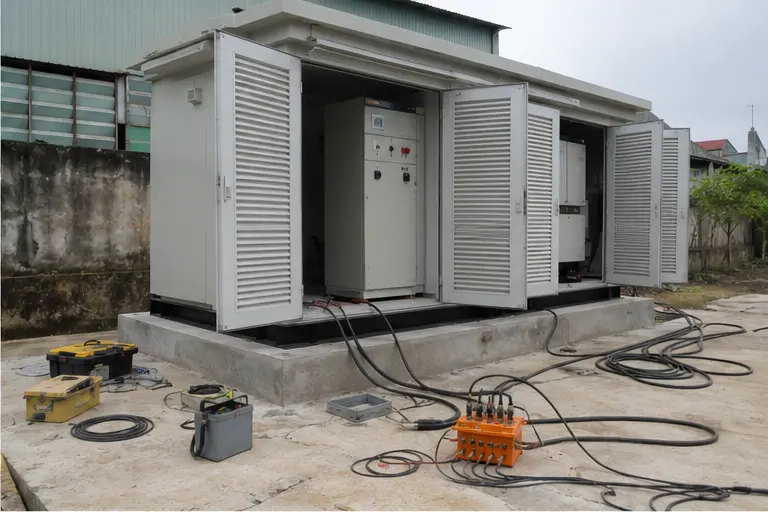
Placement and testing
The unit is set on its prepared concrete foundation and levelled. Level matters mechanically and electrically: an out-of-level enclosure loads the base frame unevenly, stresses door seals and can leave standing water on the roof, while an out-of-level oil-immersed transformer sits with an inaccurate oil-level reading. Once bolted down, insulation resistance is measured on the MV and LV sides, transformer ratio and vector group are verified, and mechanical interlocks between switch, earth switch and cable-compartment access are proved by operation. Protection settings are checked against the grading study. These checks belong here, before the cable trench is closed and access is restricted.
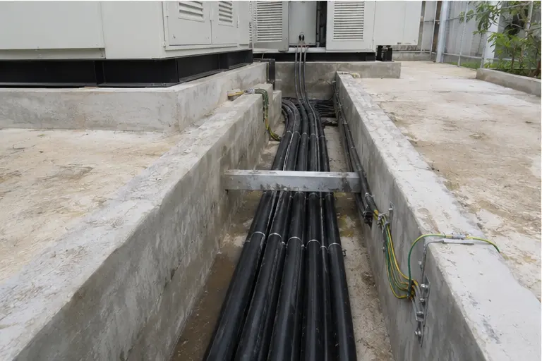
Cable and earthing work
MV and LV cables are pulled, terminated and glanded, and the earthing system is completed. Pulling tension and sidewall pressure are controlled so that conductor and insulation are not damaged inside bends; the minimum bending radius applies at the gland plate as much as in the trench. MV terminations depend on clean screen cut-back and correct stress-cone seating, and cable screens are bonded to the enclosure earth bar with a conductor rated for the earth-fault duty. The external earth electrode is connected and its resistance measured, with step and touch potential assessed for a publicly accessible outdoor location. Gland plates are sealed to maintain the declared IP rating.
Completed configuration
The completed arrangement shows the enclosure fenced, labelled and closed. Fencing and clearance distances are part of the safety case for an outdoor MV installation on an industrial site where non-electrical staff work nearby. Before energisation the system is proved as a chain: earth continuity from each enclosure part back to the main bar, protection tested by injection through relay, CT circuit and trip coil, and interlocks confirmed. Energisation is staged, with the transformer charged unloaded first and load applied progressively while temperatures, LV voltage and any monitoring outputs are observed. Warning signage, access control and as-installed schedules complete the handover package.
Specification options
For a comparable enquiry, MARS can configure the voltage ratio and tapping range, transformer capacity, vector group and impedance, and copper or aluminium windings. The transformer can be oil-immersed or cast-resin dry-type, with insulation and temperature class chosen against the plant’s fire strategy and the enclosure ventilation. MV switching can be an SF6 or solid-insulated ring main unit, or an air-insulated metal-clad panel where future extension is expected. LV assemblies can be supplied in the required form of separation with the short-circuit withstand rating the site demands. Enclosures can be specified for IP rating, corrosion protection class and coating system, with forced ventilation, anti-condensation heating and lighting. Protection and monitoring interfaces can include winding-temperature indication, alarm contacts and Modbus, IEC 61850 or DNP3 communication.
What we need to quote a comparable system
Send as many of the following as you have. Missing items are not a problem — we will ask.
- Single-line diagram, or the intended incoming and outgoing arrangement
- Incoming voltage and tapping range, and the outgoing LV voltage and system earthing
- Required transformer capacity and the plant's load profile, including motor starting duty
- System fault level at the point of connection and the required withstand rating and duration
- Number, size and type of MV and LV cables, and their entry direction
- Protection philosophy and any grading study or utility relay settings
- Local utility or network operator specification and approval requirements
- Site ambient temperature range, humidity, altitude and pollution or salinity level
- Enclosure IP rating, corrosion class, coating specification and any colour requirement
- Communication protocol and the plant SCADA or monitoring interface required
- Foundation and trench arrangement, site access route and available lifting capacity
- Delivery terms, destination port, documentation language and test certificates required