Key takeaways
- A standard 480 to 208 transformer wiring diagram connects a 480V 3-wire Delta primary to a 208Y/120V 4-wire Wye secondary with a 30-degree phase displacement.
- The secondary neutral (X0) creates a Separately Derived System per NEC 250.30, requiring both a system bonding jumper and a grounding electrode conductor.
- A 75 kVA 480V to 208Y/120V unit draws 90.2 A rated primary full-load current and supplies 208.2 A secondary line current.
- Operating in reverse using a 208 to 480 3 phase transformer wiring diagram requires careful evaluation of primary inrush current and neutral floating risks under NEC 450.11(B).
- Primary tap changers provide voltage compensation of plus or minus 2.5% to 5% without altering the internal phase angular relationship.
Quick answer: A 480 to 208 transformer wiring diagram illustrates how a three-phase 480 V Delta source connects to primary terminals H1, H2, and H3, while the secondary side provides 208Y/120 V power via terminals X1, X2, X3, and neutral X0. In commercial and industrial facilities, this configuration steps down high-efficiency feeder voltage to supply standard 120 V single-phase receptacle circuits and 208 V three-phase equipment.
Low-voltage dry-type distribution transformers represent the backbone of commercial building power distribution. Stepping down 480 V to 208Y/120 V enables engineers to transport bulk power through risers and distribution feeders at lower current levels, minimising conductor cross-sections and voltage drop before distributing usable branch circuit voltage. Correct field implementation requires precision: misinterpreting terminal schematics, overlooking system bonding jumper requirements, or incorrectly configuring voltage taps leads to phase imbalances, circulating neutral currents, and dangerous touch potentials.
Understanding the Standard 480 to 208 Transformer Wiring Diagram
A standard 480 to 208 transformer wiring diagram represents a Delta-primary, Wye-secondary configuration, classified by IEEE C57.12.00 Table 5 as an angular displacement of 30 degrees where low-voltage terminals lag high-voltage terminals. The three-phase high-voltage supply lines (A, B, C) terminate directly onto primary terminals H1, H2, and H3. Because the primary is wound in Delta, there is no high-voltage neutral conductor required from the upstream distribution board, reducing cable trench and conduit congestion.
On the secondary side, three separate winding coils connect at a common star junction, establishing the neutral terminal marked X0. Terminals X1, X2, and X3 deliver the active secondary phases. Measuring line-to-line across any two active terminals yields 208 V. Measuring line-to-neutral from any phase to X0 yields 120 V (calculated as 208 V divided by the square root of 3). For engineers reviewing schematic layouts, our guide to transformer wiring schematics and vector groups explains the international terminal conventions and graphic symbols governing these connections.
Terminal Designations, Tap Adjustments, and Secondary Neutral Grounding
Terminal markings follow ANSI/IEEE standards: high-voltage windings use the prefix H, while low-voltage windings use the prefix X. Most industrial dry-type units incorporate de-energised full-capacity taps on the primary windings, typically configured as two 2.5% Full Capacity Above Normal (FCAN) and four 2.5% Full Capacity Below Normal (FCBN) positions. If field measurements indicate a consistent supply voltage of 456 V instead of the nominal 480 V, technicians relocate the primary jumper links to the 5% below-normal tap terminal lugs. This action restores the secondary line-to-line voltage to the required 208 V without compromising core saturation limits.
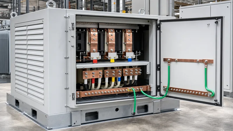
Secondary earthing constitutes the most critical safety element of the 480 to 208 transformer wiring diagram. Under NFPA 70 (NEC) Article 250.30, a Delta-Wye transformer creates a Separately Derived System. Terminal X0 must be established as an earthed circuit conductor through three mandatory field connections:
- System Bonding Jumper (SBJ): Connects terminal X0 directly to the transformer enclosure earthing busbar to ensure low-impedance ground-fault return paths.
- Grounding Electrode Conductor (GEC): Connects terminal X0 (or the ground bus) to the building structural steel or primary grounding electrode system per NEC 250.66.
- Supply-Side Bonding Jumper: Extends alongside the secondary phase conductors to the downstream main panelboard if the first overcurrent protective device resides outside the transformer enclosure.
Step-by-Step Connection Procedure and Verification
Executing the termination requires strict compliance with lock-out/tag-out (LOTO) protocols and insulation verification prior to applying supply voltage. Following a systematic procedure ensures electrical integrity and operational safety:
- De-energise and isolate: Lock out and tag out the 480 V primary feeder breaker. Verify zero energy on incoming conductors using a calibrated multi-meter or non-contact medium-voltage proximity tester.
- Mount and bond enclosure: Position the transformer housing on vibration-isolation pads. Bond the equipment grounding conductor (EGC) from the 480 V supply raceway to the enclosure ground lug.
- Terminate primary conductors: Land Phase A, B, and C supply cables onto terminals H1, H2, and H3, torquing terminal hardware to the manufacturer nameplate torque values (typically 45–55 Nm for 1/2-inch grade 5 steel fasteners).
- Configure tap connections: Verify that the tap jumper bars on all three internal primary coils occupy identical tap positions before closing access panels.
- Establish the secondary neutral and bond: Terminate the secondary neutral cable on terminal X0. Install the system bonding jumper from X0 to the ground busbar, and terminate the grounding electrode conductor.
- Terminate secondary line conductors: Connect downstream panel feeders to X1, X2, and X3. Maintain adequate bending radius per NEC Article 312 to prevent conductor insulation stress against the internal chassis.
- Insulation resistance testing: Perform a 1000 V DC Megohmmeter test between primary-to-secondary, primary-to-ground, and secondary-to-ground. Minimum acceptable insulation resistance is 100 Megaohms per NETA ATS Table 100.5.
For a detailed breakdown of field installation best practices, refer to our comprehensive guide on how to hook up a transformer.
Full-Load Current Calculation and Conductor Sizing
Sizing circuit breakers, fuses, and raceways requires precise full-load current (FLC) calculations based on rated three-phase apparent power (kVA). Consider a standard 75 kVA dry-type transformer operating at 480 V Delta primary and 208Y/120 V secondary:
Primary Full-Load Current calculation:
I_primary = kVA / (sqrt(3) * V_primary) = 75,000 / (1.73205 * 480) = 75,000 / 831.38 = 90.21 A
Secondary Full-Load Current calculation:
I_secondary = kVA / (sqrt(3) * V_secondary) = 75,000 / (1.73205 * 208) = 75,000 / 360.27 = 208.18 A
Applying NEC Table 450.3(B) rules for primary-only overcurrent protection allows a maximum setting of 125% of rated FLC where secondary protection is omitted (90.21 A * 1.25 = 112.76 A, permitting the next higher standard rating of 125 A). If secondary protection is installed at 125% (208.18 A * 1.25 = 260.2 A, utilising a 250 A or 300 A device), the primary breaker may be sized up to 250% of rated primary FLC to clear magnetising inrush current. Cable sizing must be aligned with terminal temperature ratings (75°C column of NEC Table 310.16); full technical derivations can be verified using our transformer wire sizing guide.
Reverse Operation: 208 to 480 3 Phase Transformer Wiring Diagram Considerations
A 208 to 480 3 phase transformer wiring diagram represents reverse feeding or step-up operation, where 208 V three-phase power energises the low-voltage windings to supply 480 V loads. While standard dry-type units are theoretically bi-directional, backfeeding a Delta-Wye transformer in the field introduces distinct engineering hazards that must be addressed.
Under NEC Article 450.11(B), transformers cannot be backfed unless designated for such operation by the manufacturer. When backfeeding, what was originally designed as the secondary Wye winding becomes the primary. Terminal X0 must not be bonded to earth or connected to a system neutral. Earthing X0 on a backfed step-up bank creates a parallel path for zero-sequence currents, causing elevated core excitation losses, transformer overheating, and nuisance tripping of upstream earth-fault relays. Furthermore, energising the low-voltage side results in peak inrush currents exceeding 12 to 16 times rated FLC, frequently tripping standard thermal-magnetic breakers. For setups requiring 480 V Delta outputs or industrial motor supplies, engineers should evaluate our guide on 3 phase delta wiring diagrams or specify a purpose-built Wye-to-Delta step-up unit.
Pre-Commissioning Inspection and Verification Checklist
A structured quality check prior to initial energisation prevents phase short-circuits, incorrect rotation, and terminal overheating under load. The following engineering checklist should be verified on-site by the commissioning technician:
| Inspection Parameter | Testing Standard / Tool | Acceptance Criteria | Failure Implication |
|---|---|---|---|
| Insulation Resistance | 1000V DC Megohmmeter | > 100 MΩ (Pri-Sec, Pri-Gnd, Sec-Gnd) | Winding breakdown, phase-to-ground flashover |
| Winding Resistance | Micro-ohmmeter (Kelvin Bridge) | Phase-to-phase variance < 1.5% | Loose internal tap links, open winding turn |
| Neutral Bonding | Low-resistance Ohmmeter | X0 to Enclosure Ground < 0.1 Ω | Floating neutral, dangerous touch potentials |
| Voltage Ratio Check | Transformer Turns Ratio (TTR) Test | Within ±0.5% of calculated ratio | Incorrect tap configuration, improper output voltage |
| Fastener Torque | Calibrated Torque Wrench | Nameplate torque (e.g. 45-55 Nm for 1/2 in) | High resistance connection, terminal fire |
| Phase Rotation | Phase Sequence Meter | Clockwise A-B-C rotation at secondary line terminals | Motor reversal, equipment mechanical failure |
Next steps: specifying and sourcing
When specifying three-phase step-down distribution units for industrial substations or commercial developments, accurate procurement documentation prevents delivery delays and costly field modifications. Ensure your Request for Quotation (RFQ) specifies nominal primary and secondary voltages, kVA rating, BIL level (typically 10 kV for low-voltage systems per IEEE C57.12.01), impedance percentage (%Z), winding material (copper or aluminium), and enclosure NEMA/IP rating. Explore our high-efficiency dry type transformers and industrial oil immersed transformers. To submit your project single-line diagram and tender schedules directly to our engineering team, visit our transformer quotation page.
Frequently asked questions
What is the difference between 480V Delta and 208Y/120V Wye?
A 480V Delta connection uses three phase conductors without a neutral, delivering 480V between any two phases. A 208Y/120V Wye system uses three phase conductors and a central neutral point (X0), providing 208V line-to-line for three-phase equipment and 120V line-to-neutral for single-phase commercial branch circuits.
Should terminal X0 be bonded to ground on a 480 to 208 transformer?
Yes, terminal X0 must be bonded to the transformer enclosure ground bus via a system bonding jumper when operating as a step-down unit per NEC Article 250.30. This creates a stable earthed reference for the Separately Derived System, preventing floating neutral voltages and facilitating overcurrent device tripping during phase-to-ground faults.
Can you backfeed a 480 to 208V transformer to step up voltage?
Yes, but only if the transformer nameplate confirms suitability for step-up operation per NEC 450.11(B). When backfeeding 208V into the X terminals, do not connect or earth terminal X0; floating this terminal prevents severe circulating currents, core saturation, and unexpected breaker tripping caused by high magnetic inrush.
Why is there a 30-degree phase shift in a 480 to 208 wiring schematic?
The 30-degree phase shift is an inherent physical characteristic of connecting Delta primary windings to Wye secondary windings. As defined by IEEE and IEC vector standards, secondary line-to-neutral voltages lag the corresponding primary line-to-line voltages by 30 degrees, which must be matched if paralleling separate transformer banks.
How do you adjust primary taps if the secondary voltage is too low?
De-energise and isolate the unit, then move the primary tap links to a lower percentage tap position (Full Capacity Below Normal or FCBN). Lowering primary turns reduces the turns ratio, which raises secondary voltage back to the nominal 208Y/120V design level.
Tags: 480 to 208 transformer wiring diagram 208 to 480 3 phase transformer wiring diagram step-down transformer dry-type transformer transformer grounding


