Key takeaways
- Identify low-voltage bushings correctly using standard terminal nomenclature (X0, X1, X2, X3 per IEEE C57.12.00 or 2U, 2V, 2W, 2N per IEC 60076-1).
- Apply Belleville conical spring washers and torque low-voltage lug terminations to exact bolt manufacturer specifications (e.g., 40 Nm for Grade 8.8 M10 bolts) to prevent thermal relaxation.
- Bond the low-voltage neutral point directly to the facility earthing electrode conductor per NEC Article 250.30 or IEC 60364-5-54 when configuring a separately derived system.
- Prevent mechanical stress on transformer terminals by supporting incoming cables independently within 300 mm to 450 mm of the bushing spades.
- Verify phase rotation, insulation resistance (minimum 100 Megohms at 1000 V DC), and winding resistance balance before energising any secondary termination.
Quick answer: To connect low voltage wires to a transformer, isolate and verify zero energy on all windings, identify the low-voltage phase terminals (X1, X2, X3 or 2U, 2V, 2W) and neutral (X0 or 2N), crimp appropriately sized compression lugs onto stripped conductors, mount them to the terminal palms using Grade 8.8 or Grade 5 fasteners with Belleville conical spring washers, torque to specification, and establish the required neutral earthing bonding.
Connecting conductors to the secondary side of a distribution transformer is one of the most critical mechanical and electrical tasks during site installation. Because the low-voltage (LV) side carries significantly higher rated currents than the primary medium-voltage side—frequently ranging from 400 A to upwards of 4,000 A on industrial transformers—even fractions of a milliohm of unintended contact resistance generate destructive heat. Under full-load operation, a poorly terminated conductor will degrade bushing gaskets, accelerate conductor oxidation, and eventually trigger catastrophic phase-to-phase flashovers or phase-to-earth faults.
Whether completing a transformer installation on a dry-type commercial unit or terminating multi-conductor parallel runs on an outdoor oil-filled unit substation, engineers and electricians must adhere to strict international standards such as IEC 60076, IEEE C57.12.00, and NFPA 70 (NEC). This guide details the practical, field-proven methodology for executing reliable, low-resistance connections on transformer secondary terminals.
Low Voltage Terminal Identification and Marking Standards
Low-voltage terminals are distinguished from high-voltage terminals by their physical size, bushing insulation class, and standard alphanumerical markings. On three-phase distribution equipment, the secondary winding handles lower voltage and higher current, which requires larger cross-sectional copper or aluminium spades or stud terminals rather than the tall, ribbed porcelain or resin insulators found on the primary side.
Marking standards differ between regional conventions:
- IEEE / ANSI C57.12.00: High-voltage terminals are designated H1, H2, and H3 (with H0 if a neutral exists). Low-voltage terminals are marked X1, X2, and X3 for the active phases, and X0 designates the neutral point. In standard step-down transformers, looking at the low-voltage side from left to right, the standard physical arrangement for subtractive polarity is typically X1, X2, X3, with X0 positioned either on the far left or adjacent to X1 depending on internal bus routing.
- IEC 60076-1: Phase designations use alphanumeric sequences where capital letters signify the primary winding (1U, 1V, 1W) and lowercase or prefixed numbers signify the secondary winding (2U, 2V, 2W). The secondary neutral terminal is labelled 2N.
Before preparing any conductors, examine the transformer nameplate diagram. Nameplates explicitly indicate internal winding connections (such as Dyn11 or Delta-Wye) and terminal layouts. If you are integrating equipment configured for a specific distribution voltage, such as a 480 to 208 transformer wiring diagram, confirming the vector group ensures phase displacement between primary and secondary matches the facility distribution architecture.
Conductor Selection and Cable Preparation Best Practices
Proper conductor selection dictates the ampacity, flexibility, and physical termination method required at the transformer terminal spades. Secondary transformer circuits often require parallel conductor runs per phase to handle rated full-load currents without exceeding thermal ratings established under IEC 60287 or NEC Table 310.16.
For detailed conductor ampacity calculations and de-rating factors, consult our engineering guide on transformer wire selection and sizing. When preparing conductors for termination, adhere to these sequential technical practices:
- Conductor Stripping: Strip insulation using a calibrated stripping tool designed for the specific outer diameter. Avoid circumference-scoring cable strands with utility knives; nicked or severed outer strands reduce the cross-sectional area and concentrate mechanical shear stress under thermal cycling.
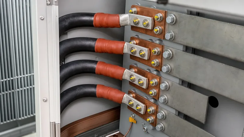
- Lug Selection: Use heavy-duty, two-hole compression (crimp) lugs complying with UL 486A-486B or IEC 61238-1. Two-hole lugs prevent rotational twisting over time, which can loosen bolted joints. For copper conductors terminating on copper or tinned copper transformer spades, specify electro-tin-plated electrolytic copper lugs.
- Bi-Metallic Terminations: If connecting aluminium conductors to copper transformer spades, use dual-rated (AL9CU) or friction-welded bi-metallic aluminium-copper lugs. Coat the aluminium strand basket immediately with an approved oxide-inhibiting compound before inserting the cable to eliminate aluminium oxide film formation.
- Compression Crimping: Employ a calibrated hydraulic crimper fitted with the exact die index specified by the lug manufacturer. Apply the full sequence of crimps starting near the lug palm and working towards the cable barrel entrance. Wipe away any displaced oxide inhibitor.
Step-by-Step: How to Connect Low Voltage Wires to Transformer
Executing the mechanical connection requires systematic isolation, inspection, and fastening procedures to ensure mechanical stability and low contact impedance.
- Perform Lockout/Tagout (LOTO) and Zero Energy Verification: De-energise both the primary medium-voltage supply and any secondary backfeed sources (such as an uninterruptible power supply or tie-breaker). Prove dead using a verified, calibrated voltage detector and apply safety grounds in accordance with NFPA 70E or EN 50110-1.
- Train and Support the Incoming Cables: Shape the secondary cables into their final pathways inside the enclosure or cable marshalling compartment. Never use the transformer bushings or spades as cantilever supports for cable weight. Secure all cables to structural strut channels or cable cleats within 300 mm to 450 mm of the terminal spade to absorb electrodynamic forces generated during short circuits.
- Clean and Prepare Contact Faces: Lightly dress the mating surfaces of the transformer copper spade and the lug palm using a non-metallic abrasive pad to eliminate surface oxidation. Never use coarse emery paper that grooves the copper. Apply a thin layer of conductive contact paste if specified by the equipment manufacturer.
- Assemble the Bolted Fastener Stack: Insert high-tensile hardware through the aligned holes. The mandatory fastener stacking sequence from bolt head to nut is: Bolt Head → Flat Washer → Transformer Terminal Spade → Cable Lug Palm → Flat Washer → Belleville Conical Spring Washer → Hex Nut. The crown (concave base) of the Belleville washer must face the flat washer, placing spring tension against the nut.
- Torque to Calibrated Settings: Hand-tighten all nuts across the phase group to align the surfaces flush. Using a calibrated click-type or digital torque wrench, tighten each bolt in an alternating cross-pattern up to 50% of the target torque, then repeat to 100% of the specified value.
- Apply Torque Seal Indicator: Draw a continuous line of tamper-evident torque seal lacquer across the bolt head, nut, and exposed thread shank. This provides immediate visual confirmation during periodic inspections that no hardware has loosened.
Mechanical Torque Specifications and Hardware Guidelines
Bolted electrical connections experience continuous thermal expansion and contraction due to load fluctuations. Without correct fastener selection and tensioning, bolted assemblies suffer from bolt stretch or joint relaxation, leading to elevated contact resistance and eventual thermal runaway.
Standard split lock washers must never be used on electrical bus connections because they deform permanently and exert inadequate follow-through force under thermal cycling. Instead, use high-strength carbon steel Grade 8.8 (metric) or Grade 5 (imperial) bolts paired with conical Belleville spring washers, or silicon-bronze fasteners where non-magnetic properties are required.
The following table outlines standard torque specifications for dry, non-lubricated steel hardware applied to copper transformer terminal palms:
| Fastener Size (Metric / Imperial) | Bolt Grade / Material | Recommended Torque (Metric - Nm) | Recommended Torque (Imperial - ft-lbs) | Minimum Lug Thickness Required (mm) |
|---|---|---|---|---|
| M8 (5/16 in - 18) | Grade 8.8 / Carbon Steel | 20 - 24 Nm | 15 - 18 ft-lbs | 3.0 mm |
| M10 (3/8 in - 16) | Grade 8.8 / Carbon Steel | 40 - 45 Nm | 30 - 33 ft-lbs | 4.0 mm |
| M12 (1/2 in - 13) | Grade 8.8 / Carbon Steel | 70 - 80 Nm | 52 - 59 ft-lbs | 5.0 mm |
| M16 (5/8 in - 11) | Grade 8.8 / Carbon Steel | 170 - 190 Nm | 125 - 140 ft-lbs | 6.0 mm |
| 1/2 in - 13 | Silicon Bronze (ASTM B99) | 55 - 60 Nm | 40 - 44 ft-lbs | 5.0 mm |
Note: If conductive joint compound or thread lubricant is applied to bolt threads, reduce nominal dry torque values by 20% to avoid over-stressing the bolt shank. Always defer to the manufacturer torque placard mounted inside the terminal cabinet.
Earthing and Neutral Bonding for Low Voltage Transformer Installation
Correct earthing during low voltage transformer installation ensures personnel safety, establishes a low-impedance ground-fault return path, and stabilises phase-to-ground system voltages. Under NEC Article 250.30 and IEC 60364-5-54, secondary windings configured as a Wye (Star) system constitute a Separately Derived System.
To bond the neutral and earth correctly:
- Main Bonding Jumper (MBJ): In a standard distribution system, the neutral terminal (X0 or 2N) must be connected to the equipment earthing conductor (enclosure) via an unspliced main bonding jumper. This connection must only occur at one single point—either inside the transformer secondary terminal compartment or within the primary low-voltage switchboard, never both. Dual bonding creates circulating stray neutral currents over metallic raceways.
- Grounding Electrode Conductor (GEC): Install an unspliced copper conductor from the transformer X0 terminal or earthing bar directly to the structural building steel, metal water piping, or dedicated foundation earthing grid. Size the GEC according to NEC Table 250.66 or regional equivalents based on the largest ungrounded secondary phase conductor cross-section.
- Equipment Grounding Conductor (EGC): Bond all incoming and outgoing metal conduits to the transformer enclosure using grounding bushings and bonding jumpers sized according to overcurrent protection ratings.
Pre-Commissioning Verification and Testing Checklist
Prior to closing the secondary breaker or energising the primary winding, perform rigorous mechanical and electrical acceptance testing. Never energise a transformer solely based on visual checks.
Review the comprehensive procedures detailed in our guide on how to test a transformer. For low-voltage terminations, execute the following checklist:
- Torque Verification: Physically re-check all bolted connections with a calibrated torque wrench set to target torque. Confirm torque-seal markings are visible and continuous.
- Phase Clearance Inspection: Measure physical air clearance between uninsulated live copper lugs, adjacent phases, and the grounded enclosure walls. For voltages up to 600 V, maintain a minimum phase-to-phase and phase-to-earth clearance of 25.4 mm (1.0 inch) through air per UL 1561 and NEMA standards.
- Insulation Resistance (Megohmmeter) Testing: Disconnect the neutral-to-ground bonding jumper temporarily. Test secondary-to-primary and secondary-to-ground insulation using a 1,000 V DC test set for 60 seconds per IEEE C57.152. Minimum insulation resistance must exceed 100 Megohms at 20°C. Re-install the bonding jumper immediately following the test.
- Phase Rotation and Continuity: Verify phase continuity across conductor runs using a low-resistance ohmmeter. Once energised at no-load, verify secondary terminal voltages (e.g., 400 V line-to-line, 230 V line-to-neutral, or 208 V line-to-line, 120 V line-to-neutral) and verify clockwise phase rotation (A-B-C / standard phase sequence) using a digital phase sequence meter before applying load.
Next steps: specifying and sourcing
When specifying distribution equipment for industrial, utility, or commercial facilities, precise terminal compartment dimensions, bushing configurations, and factory-drilled spade arrangements ensure smooth site cabling. Ensure your RFQ documentation specifies secondary cable sizes, number of parallel conductors per phase, lug hole spacing (e.g., standard NEMA two-hole spacing with 44.5 mm centres), and preferred terminal metallurgy.
Explore our engineering capabilities across dry type transformers, oil immersed transformers, and robust outdoor pad mounted transformers engineered to international standards. For custom terminal arrangements, technical submittals, or project quotation assistance, submit your single-line diagram directly through our quotation inquiry page or reach out to our engineering team via the contact page.
Frequently asked questions
how to connect low voltage wires to transformer
To connect low voltage wires to a transformer, strip the conductors without nicking strands, crimp dual-hole compression lugs, mount them to the secondary terminals (X1, X2, X3, X0) using Grade 8.8 bolts with Belleville washers, torque to manufacturer ratings, and install the required neutral bonding jumper.
Why are Belleville washers required on low-voltage transformer terminals?
Belleville conical spring washers maintain constant contact pressure as copper and aluminium expand and contract under heavy cyclic electrical loads. Standard lock washers flatten permanently, resulting in loose connections, high resistance, and terminal overheating.
Can I connect aluminium cables directly to copper transformer spades?
Aluminium cables must never touch bare copper directly due to galvanic corrosion and differential thermal expansion. Use dual-rated (AL9CU) or bi-metallic crimp lugs, apply an approved oxide-inhibiting compound, and clean contact surfaces before securing the hardware.
Where should the neutral-to-ground bond be placed for a step-down transformer?
The neutral-to-ground main bonding jumper must be installed at exactly one location: either inside the transformer secondary terminal compartment or inside the first downstream distribution switchboard, as defined by NEC 250.30 and IEC 60364.
What is the recommended bolt torque for an M12 low-voltage transformer terminal?
A standard Grade 8.8 steel M12 bolt on an electrical bus termination requires a tightening torque of 70 to 80 Nm (52 to 59 ft-lbs) under dry conditions. Always verify with the manufacturer placard before final sign-off.
Tags: transformer wiring low voltage connections cable termination electrical installation transformer maintenance


