Key takeaways
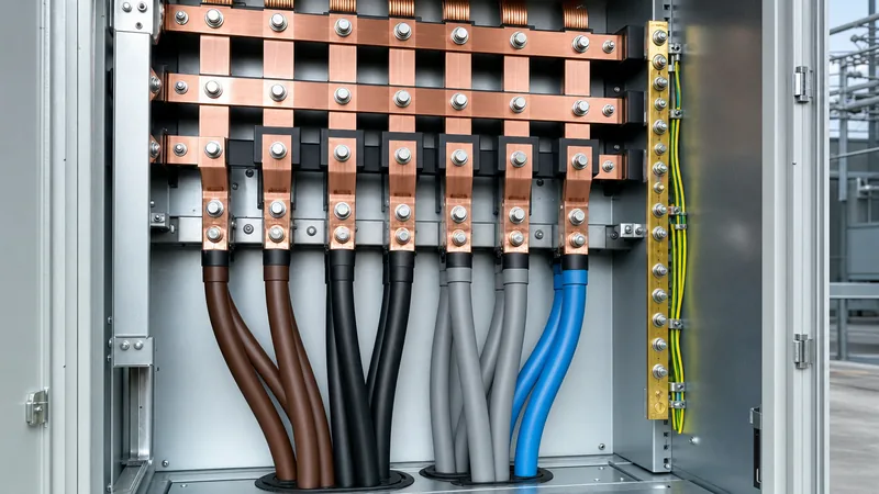
- Under international standard IEC 60445, the color code for 3 phase power designates Brown as Phase 1 (L1), Black as Phase 2 (L2), Grey as Phase 3 (L3), Blue as Neutral (N), and Green/Yellow stripes as Protective Earth (PE).
- In the United States, NFPA 70 (NEC) mandates phase identification but leaves line colours to industry convention: Black-Red-Blue for 208Y/120V systems, and Brown-Orange-Yellow for 480Y/277V systems.
- NEC Article 110.15 strictly requires the high-leg phase on a 240/120V delta system (carrying 208V to neutral) to be permanently identified with an orange tag or finish.
- Phase rotation direction (clockwise phase sequence vs counter-clockwise) cannot be determined solely by wire insulation colour; it must be verified with an instrument before commissioning rotating plant or parallel transformers.
- Legacy European installations before the 2004 CENELEC harmonisation used Red, Yellow, and Blue for active phases, requiring clear caution labelling at transition interface points per BS 7671.
Quick answer: The standard color code for 3 phase power depends on your regulatory jurisdiction: under international standard IEC 60445, Phase 1 (L1) is brown, Phase 2 (L2) is black, Phase 3 (L3) is grey, neutral is blue, and earth is green-and-yellow stripes. In North America (NEC), 208Y/120V systems typically use black, red, and blue, while 480Y/277V systems use brown, orange, and yellow.
Maintaining correct phase identification is essential for personnel safety, equipment reliability, and system performance. When wiring low-voltage distribution boards, secondary transformer connections, or heavy industrial machinery, misidentifying a phase conductor can lead to phase-to-phase short circuits, uncontrolled motor reversal, or catastrophic equipment failure during parallel bus switching. International EPC contractors, switchgear builders, and field engineers regularly encounter installations that mix regional conventions or bridge vintage and modern wiring codes. This technical guide outlines the precise conductor marking mandates across IEC, US NEC, Canadian, and Australian regulatory frameworks, examines special requirements such as high-leg delta identification, and provides an actionable phase verification protocol for field commissioning.
IEC 60445 and European Harmonised Phase Conventions
The international standard IEC 60445 (Clause 6.2.3 and Table 1) governs basic and safety principles for man-machine interfaces, marking, and identification, defining the modern standard for three-phase AC wiring across Europe, Asia, and most Commonwealth nations. Standardised under CENELEC HD 308 S2 in 2004 and integrated into national standards like the UK BS 7671 (Clause 514.4), this framework replaces legacy regional schemes with a single unified palette for low-voltage systems operating at 400V/230V.
Under IEC 60445, conductors in a standard 3 phase 4 wire system must be marked as follows:
- Phase 1 (L1): Brown
- Phase 2 (L2): Black
- Phase 3 (L3): Grey
- Neutral (N): Blue (specifically light blue)
- Protective Conductor (PE / Earth): Bi-colour Green-and-Yellow stripes (ratio between 30% and 70% coverage per IEC 60445 Clause 6.3.2)
Prior to the 2004 harmonisation, British and Commonwealth standards adhered to Red (L1), Yellow (L2), and Blue (L3), with Black as the neutral conductor and Green or Green/Yellow as protective earth. A critical safety hazard arose because legacy Black denoted neutral, whereas modern harmonised Black represents Phase 2 (active at 230V line-to-neutral). For this reason, BS 7671 Clause 514.14 mandates that whenever additions or alterations are made to installations containing both pre-harmonised and post-harmonised wiring, an unambiguous warning notice must be affixed at the distribution board stating: "CAUTION: This installation has wiring colours to two versions of BS 7671. Great care should be taken before undertaking extension, alteration or repair."
US National Electrical Code (NEC) 3 Phase Electrical Wire Color Code
The United States National Electrical Code (NFPA 70) enforces functional conductor identification rules rather than specifying rigid insulation colours for every active phase conductor. Under NEC Article 210.5(C)(1) and Article 215.12(C)(1), where a premises wiring system contains branch circuits or feeders supplied from more than one nominal voltage system, each ungrounded (hot) conductor must be identified by phase and system at all termination, connection, and splice points. The means of identification can be separate colour coding, marking tape, tagging, or other approved means, and must be permanently posted at each branch-circuit or feeder panelboard.
Despite the code flexibility for hot conductors, strict industry conventions have evolved across North America to prevent dangerous cross-voltage connection errors:
For low-voltage 208V 3 phase power and 240V/120V systems:
- Phase A (L1): Black
- Phase B (L2): Red
- Phase C (L3): Blue
- Neutral: White (mandated by NEC Article 200.6 for grounded conductors #6 AWG and smaller)
- Equipment Ground: Green or bare copper (NEC Article 250.119)
For commercial and industrial 480V 3 phase power (480Y/277V systems):
- Phase A (L1): Brown
- Phase B (L2): Orange
- Phase C (L3): Yellow
- Neutral: Grey (or white with three continuous purple stripes, per NEC 200.6(D))
- Equipment Ground: Green, green with yellow stripe, or bare copper
These distinctions protect plant equipment. Connecting a 277V lighting circuit into a panel wired with black/red/blue wiring intended for 120V loads would result in immediate component destruction and fire risk. Therefore, multi-voltage facilities must maintain explicit demarcation between 208Y/120V and 480Y/277V switchgear bays.
High-Leg Delta Systems and the Orange Conductor Rule
On four-wire delta-connected transformer secondary systems where the midpoint of one phase winding is grounded to supply 120V single-phase lighting loads, the third ungrounded phase displays a substantially higher voltage to ground. In a standard 240/120V high-leg delta configuration, two phases measure 120V to neutral, while the high leg measures 208V to neutral (calculated as 120V × √3 ≈ 207.85V).
To prevent technicians from inadvertently landing single-phase 120V loads onto this 208V phase, the 3 phase electrical wire color code is rigidly mandated by law under NEC Article 110.15 and Article 230.56:
"On a 4-wire, delta-connected system where the midpoint of one phase winding is grounded, the service conductor or busbar having the higher phase voltage to ground shall be durably and permanently marked by an outer finish that is orange in colour, or by other effective means, at each point where a connection is made if the grounded conductor is also present."
Engineers specifying custom 3 phase high leg systems must ensure that switchboards, panelboards, and motor control centres position the high-leg conductor in the centre "B" phase compartment by design (NEC 408.3(E)(1)), except where metering equipment specifically requires Phase C positioning. Failure to identify the high leg with continuous orange sleeving or thermoshrink tubing violates safety compliance and introduces life-safety risks during breaker installation.
Global Comparison of 3 Phase Wire Color Codes
A direct comparison across dominant worldwide electrical jurisdictions shows significant variation between regions, making accurate identification critical for export equipment and international field commissioning. The table below outlines standard conductor colour designations across low-voltage AC networks:
| Jurisdiction / Standard | Phase 1 (L1 / A) | Phase 2 (L2 / B) | Phase 3 (L3 / C) | Neutral (N) | Protective Earth (PE) |
|---|---|---|---|---|---|
| IEC 60445 / EN 60446 (Europe, Asia, Int.) | Brown | Black | Grey | Blue | Green / Yellow stripe |
| US NEC (NFPA 70) 208Y/120V (Convention) | Black | Red | Blue | White | Green or Bare |
| US NEC (NFPA 70) 480Y/277V (Convention) | Brown | Orange | Yellow | Grey | Green or Bare |
| Canada (CEC Part I / CSA C22.1 Rule 4-038) | Red | Black | Blue | White | Green or Bare |
| Australia & NZ (AS/NZS 3000 Table 3.4) | Red (or Brown) | White (or Black) | Dark Blue (or Grey) | Black (or Light Blue) | Green / Yellow stripe |
| Legacy UK / Commonwealth (Pre-2004 BS 7671) | Red | Yellow | Blue | Black | Green / Yellow stripe |
| GOST 18311-80 / Russia & CIS | Yellow | Green | Red | Blue | Green / Yellow stripe |
When procuring custom packaged equipment, including transformer substations and medium-to-low-voltage assemblies, consulting engineers must specify the target country's standard during the submittal review phase. This ensures that factory-installed busbar sleeving, control wiring, and secondary jumpers conform precisely to local utility and national electrical codes without requiring costly on-site retrofits.
Busbar Markings, Terminal Labeling, and Switchgear Conventions
Inside medium-voltage and low-voltage electrical switchgear, physical busbars are frequently left uninsulated for air cooling, making insulation colour codes inapplicable. In these assemblies, engineers rely on physical phase stamping, heat-shrink sleeves at landing stabs, and alphanumeric identification conforming to IEC 61439-1 or IEEE C37.20.1 standards.
For low-voltage assemblies built to international standards, busbars are marked using letters L1, L2, L3, N, PE or U, V, W for motor circuits. Where colour taping is applied to bare copper or aluminium busbars, IEC assemblies apply bands of Brown, Black, and Grey at termination points. Under IEEE and ANSI conventions, bus arrangement within switchgear enclosures is physically standardised from front-to-back, top-to-bottom, or left-to-right as viewed from the front of the switchgear: Phase A, Phase B, Phase C, and Neutral.
Transformer secondary bushings on distribution transformers follow standardized alphanumeric markings:
- IEC Terminals: High voltage marked with capital letters (1U, 1V, 1W), low voltage marked with lower case (2u, 2v, 2w, 2n).
- ANSI/IEEE Terminals: High voltage marked H1, H2, H3; low voltage marked X1, X2, X3, and X0 for neutral.
Adhering to these conventions ensures that maintenance crews can accurately isolate, measure, and megger individual windings without relying on arbitrary wire colours.
Phase Rotation Verification and Commissioning Checklist
Phase rotation direction cannot be inferred solely from wire insulation colours or terminal designations. A sequence of standard phase colours does not guarantee clockwise phase sequence at the load terminals, because utility supply feeds or upstream delta-wye transformations may invert the phase displacement. Before connecting induction motors, industrial drives, or synchronising sources into HV/LV switchgear, field technicians must follow an inspection procedure to verify phase rotation.
Engineers and commissioning teams should execute the following verification steps on all new three-phase transformer and switchboard hookups:
- De-energised Visual & Point-to-Point Continuity Check: Verify that phase marking tape or colour insulation is continuous from the transformer secondary terminals to the main circuit breaker line stabs. Ensure the neutral bus is fully isolated from the earth bus (except at the main bonding jumper per local code).
- Phase Rotation Meter Connection: Connect an analog or digital rotary field indicator (phase sequence meter conforming to IEC 61557-7) across the three phase conductors (or secondary line terminals).
- Energisation and Voltage Measurement: Energise the transformer under no-load conditions. Using a calibrated True-RMS multimeter, measure phase-to-phase voltages (e.g. 400V or 480V nominal) and phase-to-neutral voltages (e.g. 230V or 277V nominal) across all three pairs to confirm balanced supply and verify absence of a high-leg delta condition unless explicitly designed.
- Rotation Sequence Confirmation: Read the phase rotation meter. A standard clockwise sequence (L1 → L2 → L3, or A-B-C) is required for correct forward motor rotation. If the meter indicates a counter-clockwise (reverse) sequence, de-energise and lock out the system, then swap two incoming phase conductors (e.g., L1 and L3) to achieve proper clockwise rotation.
- Permanent Tagging: Apply durable, UV-resistant vinyl or heat-shrink markers to all phases at the termination lugs, ensuring labels match the confirmed rotation profile.
Next steps: specifying and sourcing
When preparing equipment specifications or requesting bids for custom dry-type transformers, oil-immersed distribution units, or modular substations, clearly state the required conductor colour-coding standard, terminal nomenclature, and busbar tagging scheme in your scope of work. Specifying whether secondary outputs must conform to IEC 60445, NFPA 70 conventions, or regional standards eliminates costly re-identification during site acceptance testing.
Our engineering design department routinely builds distribution transformers and packaged switchgear tailored to international utility specifications and site-specific wiring mandates. To discuss your project parameters or submit single-line diagrams for technical evaluation, submit your design files through our transformer quotation request page or contact our technical sales specialists directly.
Frequently asked questions
What is the standard color code for 3 phase power in Europe?
Under IEC 60445, the European standard color code for 3 phase power is Brown for Phase 1 (L1), Black for Phase 2 (L2), Grey for Phase 3 (L3), Blue for Neutral, and Green/Yellow stripes for Protective Earth. This harmonised standard has been mandatory across all CENELEC member states since 2004.
What are the 3 phase electrical wire colors in the United States?
In the United States, 208Y/120V systems conventionally use Black for Phase A, Red for Phase B, Blue for Phase C, White for Neutral, and Green for Ground. Higher-voltage 480Y/277V systems use Brown for Phase A, Orange for Phase B, Yellow for Phase C, Grey for Neutral, and Green for Ground.
Why is the high leg on a 3 phase delta system colored orange?
NEC Article 110.15 requires the high leg of a 240/120V delta system to be marked with orange insulation or tagging because it carries 208V to ground, unlike the other two phases which carry 120V. The orange colour prevents electricians from inadvertently connecting standard 120V equipment to this higher-voltage conductor.
Can phase rotation be determined strictly by wire color?
No, wire colour indicates conductor assignment but does not guarantee phase rotation direction. Upstream utility line swaps, distribution transformer vector group configurations, and wiring terminations can alter rotation sequence, requiring verification with an approved phase sequence rotation meter before starting equipment.
What colour was Phase 1 before European wire colour harmonisation?
Prior to the 2004 European harmonisation under BS 7671 and IEC standards, Phase 1 was Red, Phase 2 was Yellow, and Phase 3 was Blue, with Black used as Neutral. Where legacy and harmonised wiring exist in the same facility, caution labels must be installed to prevent confusing legacy Black neutral conductors with modern Black Phase 2 conductors.
Tags: color code for 3 phase power 3 phase electrical wire color code three phase wiring electrical standards industrial electrical


