Key takeaways
- Insulation testing applies a stable direct-current voltage to quantify leakage current through dielectric materials and verify equipment safety.
- Standard insulation resistance test voltages range from 500 V DC for equipment rated under 250 V up to 5,000 V or 10,000 V DC for assets rated above 15 kV.
- Measured insulation resistance values double for every 10 degrees Celsius drop in temperature, requiring normalisation to a 20 degrees Celsius baseline.
- A Polarization Index (10-minute to 1-minute resistance ratio) above 2.0 indicates dry, healthy insulation, whereas values below 1.5 signal moisture or contamination.
- Effective testing requires isolating terminals, shorting winding clusters, and utilising the instrument guard terminal to eliminate surface leakage errors.
Quick answer: Insulation testing evaluates the dielectric integrity of electrical apparatus by applying a controlled direct-current voltage and measuring micro-ampere leakage currents across insulating barriers. Acceptable baseline values for medium- and high-voltage power transformers typically exceed 1,000 megohms when corrected to 20°C, with a Polarization Index above 2.0 verifying the absence of harmful moisture and particulate contamination.
In electrical power generation, transmission, and heavy industrial distribution, dielectric degradation remains the leading catalyst for catastrophic asset failure. Whether evaluating new apparatus during factory acceptance or assessing aged plant, routine diagnostic evaluation prevents unscheduled outages and personal injury. This comprehensive technical guide details the methodology of dielectric evaluation, aligned with international standards such as IEEE C57.12.90, IEEE 43, and IEC 60076-1. For a complete overview of broader testing frameworks, refer to our comprehensive guide on how to test a transformer.
What is insulation testing in electrical systems?
Insulation testing is a non-destructive diagnostic procedure that applies a regulated direct-current (DC) potential across non-energised electrical conductors and earth to determine dielectric resistance. In any plant asset, solid materials such as pressboard, cellulose paper, casting resin, and cross-linked polyethylene (XLPE) prevent current from migrating between live phases or to the grounded metallic chassis. Over operational life, electrical stress, ambient moisture, mechanical vibration, and thermal cycling degrade these barriers.
When performing ir testing electrical diagnostics, the total current flow through the insulating structure consists of three distinct physical components:
- Capacitive charging current: A high-magnitude current that decays rapidly (within milliseconds to a few seconds) as the physical geometry of the conductor-insulator system acts as a charging capacitor.
- Dielectric absorption current: A polarising current resulting from molecular dipole realignment within the dielectric, decaying exponentially over several minutes.
- Conduction or leakage current: A steady-state current that flows through the volume of the insulation material and over its external surface paths to ground.
The instrument calculates resistance in megohms (MΩ) or gigohms (GΩ) using Ohm's law ($R = V / I$). Because the capacitive and absorption currents decay asymptotically over time, the observed resistance climbs throughout the test cycle. An accurate diagnostic reading requires recording measurements at standardised intervals, which is thoroughly examined in our guide on checking insulation resistance.
Recommended test voltages for a high voltage insulation test
Standard test voltages for a high voltage insulation test depend strictly on the nominal operational voltage class and the dielectric medium of the equipment under test. Applying insufficient voltage fails to stress micro-voids and tracking paths, while excessive potential risks puncturing aged or weakened dielectric barriers. Technical committees such as IEEE and industry testing associations publish structured voltage matrices to govern field testing.
In accordance with IEEE 43-2013 and standard acceptance testing specifications Table 100.5, the DC potential applied during routine evaluation must correspond directly to the rated root-mean-square (RMS) AC operating potential of the winding or apparatus:
| Apparatus Nominal Rating (V AC RMS) | Applied DC Test Potential (V DC) | Recommended Minimum Resistance Threshold (MΩ) |
|---|---|---|
| Below 250 V | 500 V | 25 MΩ |
| 250 V to 1,000 V | 1,000 V | 100 MΩ |
| 1,001 V to 5,000 V | 2,500 V | 1,000 MΩ |
| 5,001 V to 15,000 V | 5,000 V | 5,000 MΩ |
| 15,001 V to 35,000 V | 5,000 V to 10,000 V | 10,000 MΩ |
| Above 35,000 V | 10,000 V to 15,000 V | 20,000 MΩ |
For factory acceptance testing on power transformers and primary medium-voltage distribution apparatus, test voltages are commonly ramped incrementally to identify dielectric breakdown points before sustained voltage dwells are executed.
Acceptable values for insulation resistance test across equipment classes
Acceptable values for insulation resistance test procedures must always be corrected to a standard reference temperature of 20°C (or 40°C depending on the standard) prior to engineering acceptance. Because insulation resistance is inversely proportional to temperature, a warm transformer exhibits significantly lower resistance than a cold unit, even if the physical dielectric is completely healthy. As a general engineering rule of thumb, insulation resistance halves for every 10°C increase in winding temperature, or conversely doubles for every 10°C reduction.
To calculate the temperature-corrected resistance ($R_{20}$) from the observed resistance ($R_T$) measured at temperature $T$ (in °C), engineers utilize the standard Arrhenius-based compensation formula:
$$R_{20} = R_T \times 2^{\frac{T - 20}{10}}$$
For liquid-immersed transformers, conservative international field practice enforces the historical standard of $R_{1\text{ min}} \ge (kV + 1)$ megohms per unit, where $kV$ represents the rated phase-to-phase operating voltage. However, modern high-integrity equipment routinely exhibits values orders of magnitude higher. For example, a newly commissioned 33 kV system with dry cellulose and degassed dielectric oil will display readings exceeding 3,000 MΩ at 20°C. In contrast, readings falling below 100 MΩ on apparatus rated above 5 kV indicate advanced thermal ageing, moisture contamination, or degraded fluid dielectric, necessitating validation via transformer oil testing standards.
Step-by-step transformer insulation testing procedure
Executing an insulation resistance evaluation on medium- and high-voltage transformers requires systematic isolation, grounding, and connection management to ensure operator safety and measurement accuracy. Stray surface leakage currents across porcelain or polymer bushings can distort readings by several orders of magnitude if not properly mitigated.
- Safety clearance and atmospheric recording: De-energise the equipment, verify zero energy state with an approved potential indicator, apply safety grounds, disconnect external busbars and neutral cables, and log ambient temperature and relative humidity.
- Terminal grouping and short-circuiting: Interconnect all phases of each winding cluster using conductive jumpers. Short the high-voltage bushings (H1, H2, H3) together, and short the low-voltage bushings (X1, X2, X3, X0) together. This equalises potential and eliminates inter-turn winding inductance.
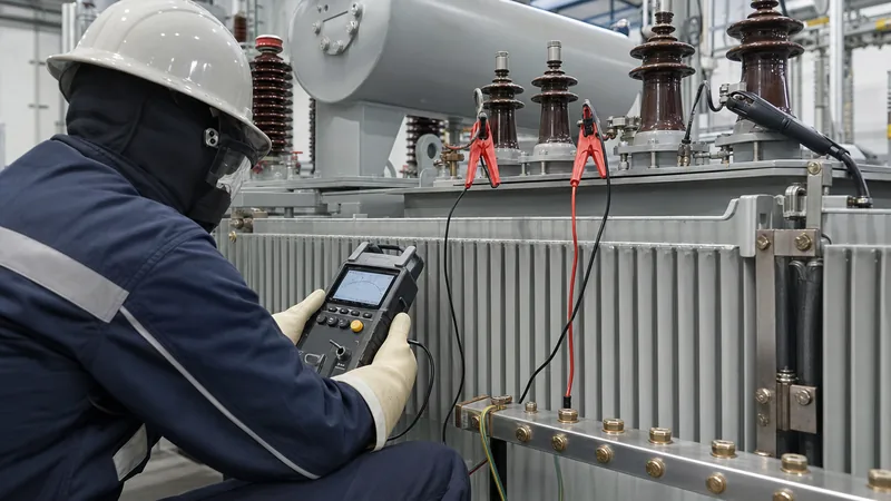
- Instrument connection and guard terminal utilization: Attach the test set line lead to the winding under test and the earth lead to the transformer metallic ground boss. To neutralise surface contamination tracking across bushing skirts, wrap a bare copper wire around the porcelain collar and connect it directly to the instrument Guard (G) terminal.
- Primary winding to secondary plus earth (HV to LV + GND): Apply the rated DC test potential for 10 consecutive minutes. Record instantaneous resistance values at 15 seconds, 30 seconds, 60 seconds (1 minute), and every minute up to 10 minutes.
- Secondary winding to primary plus earth (LV to HV + GND): Ground the high-voltage winding cluster, transfer the test lead to the low-voltage cluster, and execute a matching 10-minute test cycle.
- Inter-winding insulation (HV to LV, ungrounded): Connect the line lead to the high-voltage cluster, the earth/return lead to the low-voltage cluster, and connect the transformer tank ground to the instrument guard terminal to isolate the internal barrier.
- Controlled discharge: Following test termination, discharge all stored capacitive charges to earth using a grounded discharge stick for at least four times the total duration of voltage application.
These procedural steps apply uniformly to cast-resin units, such as an industrial dry-type transformer, as well as outdoor distribution units, such as a utility oil-immersed transformer.
Diagnostic indices: Polarization Index (PI) and Dielectric Absorption Ratio (DAR)
Diagnostic ratios such as the Polarization Index (PI) and Dielectric Absorption Ratio (DAR) evaluate insulation health independent of asset physical dimensions and temperature variations. Because both numerator and denominator values are captured during the same continuous test run on the same apparatus, thermal effects cancel out, yielding a pure metric of molecular polarization.
The Polarization Index is defined as the ratio of the 10-minute resistance measurement to the 1-minute resistance measurement ($PI = R_{10\text{ min}} / R_{1\text{ min}}$). In a clean, dry insulation structure, the absorption current continues to diminish over the entire 10-minute window, resulting in a steady upward climb in total observed resistance. Conversely, if moisture or conductive contaminants dominate the dielectric structure, the steady-state conduction leakage current swamps the absorption current within the first minute, causing the 10-minute reading to remain nearly flat.
- Dangerous ($PI < 1.0$): Indicates immediate dielectric hazard, severe moisture saturation, or active conductive tracking.
- Questionable ($1.0 \le PI < 1.5$): Indicates substantial contamination, thermal breakdown, or degradation of insulating varnishes.
- Good ($2.0 \le PI < 4.0$): Denotes clean, moisture-free, structurally sound dielectric systems per IEEE 43 guidelines.
- Excellent ($PI > 4.0$): Exemplifies pristine factory-cured solid casting or completely dried, high-grade insulation barriers.
The Dielectric Absorption Ratio (DAR) provides an accelerated 60-second diagnostic metric calculated as $DAR = R_{60\text{ s}} / R_{30\text{ s}}$. A DAR value below 1.25 warrants remedial drying or fluid treatment, while values above 1.6 confirm solid dielectric health.
Common causes of insulation failure and troubleshooting
Dielectric degradation in industrial and utility equipment is accelerated by the synergistic interaction of thermal stress, moisture ingress, chemical oxidation, and mechanical displacement. Left undetected by scheduled diagnostic routines, localized dielectric weakness progresses rapidly into catastrophic phase-to-earth faults.
Moisture represents the primary degradation accelerator within solid paper and synthetic resin systems. Water molecules degrade cellulose polymer chains via hydrolytic breakdown, reducing mechanical tensile strength and elevating dielectric loss factor ($\tan \delta$). In liquid-filled apparatus, moisture shifts between solid pressboard insulation and the surrounding insulating oil as operational temperatures fluctuate. This thermal cycling reduces the dielectric breakdown voltage of the fluid barrier.
To troubleshoot anomalous test results in the field, follow this structured diagnostic protocol:
- Persistently low resistance across all terminals: Clean all external bushing surfaces with approved solvents to eliminate conductive salt or carbon films; re-test utilising the instrument guard terminal.
- Unbalanced inter-phase readings: Isolate internal tap changer contacts and terminal boards to identify whether the low reading originates in the winding coils or the physical tap selector assembly.
- Flat or descending PI curve ($PI < 1.2$): The asset requires physical de-moisturisation. For liquid-insulated units, initiate vacuum oil dehydration and paper dry-out cycles before re-energisation.
Next steps: specifying and sourcing
When specifying distribution equipment, packaged substations, or large power apparatus for mission-critical infrastructure, rigorous insulation testing protocols must be embedded directly into project procurement technical specifications. Engineering drawings and tender documents should specify factory acceptance test (FAT) routines aligned with IEC 60076-1 and IEEE C57.12.90, including full dielectric absorption profiles, lightning impulse test withstand levels (BIL), and certified baseline IR benchmarks.
Our engineering team designs and manufactures high-performance transformers, substations, and medium-voltage switchgear engineered to maintain superior dielectric integrity across demanding operating environments. To discuss factory test certifications or submit tender specifications for your upcoming capital projects, request an engineering quotation through our transformer quotation portal or connect with our application engineers on our technical contact page.
Frequently asked questions
What is the acceptable value for an insulation resistance test?
An acceptable insulation resistance value for medium-voltage electrical equipment is generally 1 megohm per kilovolt of rated operating voltage plus 1 megohm, with modern equipment typically exceeding 1,000 megohms at 20 degrees Celsius. Acceptance also requires a Polarization Index ratio of 2.0 or greater.
What is the difference between an insulation resistance test and a high-potential (Hi-Pot) test?
An insulation resistance test applies a non-destructive direct-current voltage to quantify leakage resistance in megohms, whereas a high-potential test applies a higher stress voltage (often 2 to 3 times rated voltage) to prove dielectric withstand capability without flashover.
Why does insulation resistance decrease as temperature increases?
Insulation resistance decreases with temperature because elevated thermal energy excites free electrons and ionises internal charge carriers within the insulating material, lowering electrical resistivity. Standard industry practice requires mathematically normalising all measured resistance readings to a 20 degrees Celsius baseline.
What role does the guard terminal play during an insulation resistance test?
The guard terminal bypasses stray surface leakage currents around the instrument measuring circuit, preventing surface contamination on bushings or cables from distorting the true volumetric resistance of the insulation material. Connecting the guard wire to a conductive collar ensures accurate internal readings.
What causes a Polarization Index (PI) value to fall below 1.5?
A Polarization Index below 1.5 is caused by excessive moisture ingress, conductive surface contamination, or severe thermal degradation of the dielectric material. These factors cause high steady-state leakage currents that overwhelm the absorption current within the initial 60 seconds of testing.
Tags: insulation testing ir testing electrical values for insulation resistance test high voltage insulation test


