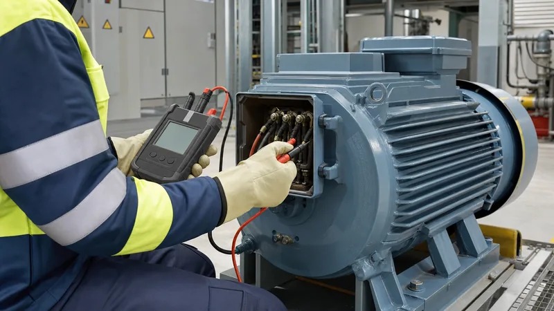
Key takeaways
- A motor insulation test applies a stabilised direct-current (DC) voltage to evaluate the dielectric integrity of stator and rotor windings against ground and between phases.
- IEEE Standard 43-2013 mandates minimum test voltages ranging from 500 V DC for motors rated under 1,000 V up to 5,000–10,000 V DC for high-voltage machines rated above 12,000 V.
- Measured insulation resistance must be normalised to a standard reference temperature of 40°C using the Arrhenius-based halving rule for every 10°C change in temperature.
- A Polarisation Index (PI) value above 2.0 and a Dielectric Absorption Ratio (DAR) above 1.4 confirm clean, dry, and healthy dielectric winding insulation.
- Routine insulation diagnostics protect upstream power distribution equipment, including medium-voltage switchgear and distribution transformers, from damaging short-circuit faults.
Quick answer: A motor insulation test assesses the electrical integrity of motor winding insulation by applying a high direct-current (DC) voltage to measure leakage current and calculate insulation resistance in megohms (MΩ). Performed in accordance with IEEE 43 and IEC 60034-27, it identifies thermal degradation, moisture contamination, and physical cracking before phase-to-ground or phase-to-phase flashovers occur.
In industrial facilities, electric motors operate as the primary mechanical drivers, frequently fed directly from dedicated medium-voltage (MV) and low-voltage (LV) substations. When stator or rotor winding insulation breaks down, the resulting high-energy electrical fault causes immediate production stoppages and subjects upstream equipment—such as feeder cables, protective circuit breakers, and distribution transformers—to severe thermal and mechanical short-circuit stresses. Establishing a rigorous testing protocol provides critical predictive health data, preventing catastrophic machine burnouts and extending asset operational life.
Why Electric Motor Insulation Testing is Critical for Power Systems
An electric motor insulation test safeguards electrical distribution networks by detecting latent dielectric degradation before ground faults trigger plant-wide trip events. Dielectric breakdown accounts for over 35% of all induction and synchronous motor failures in continuous-process industries. Operating stress weakens winding insulation through a combination of thermal, electrical, ambient, and mechanical factors (the TEAM framework).
Thermal stress occurs when motors run continuously near full-load thermal limits or encounter frequent across-the-line starting cycles, which embrittles organic resin systems. Electrical stress stems from line transients, switching surges, and rapid voltage rise times (dV/dt) caused by variable-frequency drives (VFDs). Ambient stress introduces humidity, conductive chemical dust, and oil mist onto winding end-turns. Finally, mechanical vibration and electromagnetic cyclic loading cause stator coils to fret against stator core slot edges.
When winding insulation deteriorates to an unserviceable level, the failure mode rarely stays isolated inside the machine. A dead ground fault draws thousands of amperes of ground-fault current, causing severe voltage sags across the main busbar. For engineers managing integrated electrical infrastructures, referencing guidelines on checking insulation resistance ensures reliable coordination between rotating machine health and upstream protection devices.
Standards and Voltage Guidelines for Motor Insulation Resistance Testing
Standardised motor insulation resistance testing requires selecting specific DC potential levels calibrated to the rated line-to-line operating voltage of the machine. The two globally accepted engineering standards governing these practices are IEEE 43-2013 (IEEE Recommended Practice for Testing Insulation Resistance of Electric Machinery) and IEC 60034-27-4.
Unlike alternating current (AC) high-potential (HiPot) proof tests, an insulation resistance diagnostic test uses direct current to eliminate continuous capacitive charging currents, allowing the instrument to measure true conduction and absorption leakage currents. Testing voltages are tiered according to winding voltage classes. Applying an excessively high DC voltage risks puncturing aged or delicate ground-wall insulation, whereas an inadequate voltage level fails to polarise the dielectric, yielding inaccurate measurements.
The following table outlines standard DC test voltages and historic minimum insulation resistance acceptance thresholds normalised to a reference temperature of 40°C, in compliance with IEEE 43-2013 recommendations:
| Motor Winding Rated Voltage (V Line-to-Line) | Applied DC Test Voltage (V) | Minimum Insulation Resistance at 40°C (MΩ) | Dielectric Type / Machine Class |
|---|---|---|---|
| < 1,000 V | 500 V DC | 5 MΩ | Random-wound stator coils and modern form-wound machines |
| 1,000 V – 2,500 V | 500 V – 1,000 V DC | 100 MΩ | Form-wound coils built post-1970 (thermosetting resin) |
| 2,501 V – 5,000 V | 1,000 V – 2,500 V DC | 100 MΩ | Form-wound high-voltage machines (epoxy-mica systems) |
| 5,001 V – 12,000 V | 2,500 V – 5,000 V DC | 100 MΩ | Form-wound high-voltage machines (Class F / H insulation) |
| > 12,000 V | 5,000 V – 10,000 V DC | 100 MΩ | High-voltage generation and utility-scale motors |
| All ratings (pre-1970) | As above per voltage class | Rated kV + 1 MΩ | Older thermoplastic/asphalt-mica insulation systems |
For modern machines manufactured with thermosetting insulation (such as vacuum pressure impregnated epoxy-mica), IEEE 43 recommends 100 MΩ as the baseline threshold for form-wound windings, and 5 MΩ for most random-wound windings rated below 1,000 V.
Key Diagnostic Metrics: IR, Polarisation Index, and Absorption Ratio
A comprehensive diagnostic evaluation relies on three distinct measurements: spot Insulation Resistance (IR), the Polarisation Index (PI), and the Dielectric Absorption Ratio (DAR). Each metric captures different aspects of dielectric performance over time under applied direct-current stress.
When a DC potential is applied across winding insulation, total current ($I_{Total}$) comprises four discrete components: capacitive charging current ($I_c$), dielectric absorption current ($I_a$), surface leakage current ($I_l$), and volume conduction current ($I_g$). Capacitive current decays rapidly within seconds. Dielectric absorption current reflects the alignment of molecular dipoles within the resin-mica matrix and decays slowly over 10 to 15 minutes. Surface leakage and conduction currents remain constant over time and are heavily governed by surface contaminants, carbon tracks, and moisture ingress.
The Polarisation Index is defined as the ratio of the insulation resistance recorded at 10 minutes to that recorded at 1 minute:
PI = R10min / R1min
In a healthy, dry insulation system, absorption current continues to decay throughout the test, driving the overall resistance upward and yielding a PI value typically exceeding 2.0. Conversely, if windings are saturated with moisture or coated in conductive grime, the flat leakage current dominates immediately; resistance fails to rise between the 1-minute and 10-minute marks, resulting in a PI close to 1.0. For fast evaluations on smaller machines, the Dielectric Absorption Ratio uses the ratio of resistance recorded at 60 seconds relative to 30 seconds (DAR = R60s / R30s), where a value above 1.4 confirms sound insulation. To review corresponding procedures on electrical equipment, examine our technical analysis of insulation testing procedures and standards.
Crucially, all measured insulation resistance values must undergo temperature correction to 40°C before historical trending. As temperature climbs, molecular thermal activity increases conductive electron mobility, reducing insulation resistance exponentially. The standard temperature correction formula applied is:
R40°C = KT × RT
Where KT = (0.5)(40 - T)/10, assuming insulation resistance halves for every 10°C rise in temperature (valid between 10°C and 60°C).
Step-by-Step Procedure for a Motor Insulation Test
Executing a motor insulation test requires systematic adherence to safety lock-out procedures, proper instrument configuration, and post-test discharging to prevent electric shock and instrument damage. Testing should only be undertaken by qualified electrical personnel using a calibrated megohmmeter.
- Isolate and Lock Out Power: De-energise the motor feeder at the switchgear or motor control centre (MCC). Implement Lockout/Tagout (LOTO) protocols, visually verify open switch contacts, and confirm the absence of AC and DC voltage on all phases using a rated multimeter or proximity detector.
- Disconnect Peripheral Electronics: Disconnect external solid-state components, including VFD output leads, surge protective devices (SPDs), soft-starters, and RTD temperature sensor wiring. High-voltage DC test pulses will puncture the gate junctions of inverter-grade IGBTs and damage internal sensor elements.
- Discharge Residual Capacitance: Connect an earthing stick to the motor frame (chassis ground) and touch all winding terminals (U, V, W or T1, T2, T3) for a minimum of 5 minutes to neutralise any latent static charges.
- Clean and Inspect Terminals: Inspect the motor terminal junction box. Clear away moisture, grease, and carbon dust from terminal standoff insulators. Wipe down connection studs with an approved dielectric solvent to eliminate surface tracking paths.
- Connect the Megohmmeter: Attach the meter's Earth (E) lead firmly to the unpainted motor frame or main ground stud. Attach the Line (L) lead to the phase winding under test. If testing one phase with the others isolated, connect the remaining two phases together and ground them. Where high humidity or surface contamination is present, wrap a bare copper guard wire around the terminal bushing porcelain and connect it to the meter's Guard (G) terminal to divert surface leakage currents away from the measuring circuit.
- Apply Test Voltage and Log Data: Select the correct DC voltage based on machine rating. Initiate the test, recording the insulation resistance value at 30 seconds, 60 seconds, and continuously up to 10 minutes. Observe the resistance profile: an upward-sloping resistance curve over time denotes normal dielectric polarisation.
- Safely Discharge the Winding: Upon completing the test, keep the grounding leads attached. Modern insulation absorbs substantial energy; discharge the winding to ground for a period at least four times the test duration (minimum 15 to 40 minutes for a 10-minute test) before direct physical handling.
Common Failure Modes and Interpreting Test Results
Interpreting test readings requires distinguishing between localized surface leakage and systemic ground-wall insulation breakdown. Low resistance readings can point to moisture ingress, thermal embrittlement, chemical tracking, or mechanical fractures within the slot insulation.
When an insulation test displays an unusually low 1-minute resistance reading (for instance, < 2 MΩ on a 4.16 kV stator) combined with a flat Polarisation Index hovering near 1.0 to 1.1, moisture absorption is almost universally the root cause. If the machine has stood idle in a humid environment without space heaters active, moisture settles into microscopic pores in the resin matrix. In most cases, controlled oven baking or passing low-voltage DC current through the windings drives out absorbed water, restoring insulation resistance above baseline criteria.
In contrast, if the 1-minute resistance remains moderately elevated (e.g., > 50 MΩ) but the PI is below 1.5, this characteristic indicates dry thermal embrittlement, aged resin-binder loss, or severe accumulation of non-conductive dirt. Stator winding diagnostics frequently mirror the test profiles seen during high-voltage transformer commissioning and maintenance, as detailed in our guide on how to test a transformer. Regular trending across six- to twelve-month intervals provides actionable insights, pinpointing progressive degradation long before catastrophic phase-to-ground flashovers occur.
Next steps: specifying and sourcing
When specifying and sourcing medium-voltage and low-voltage distribution assets to supply critical rotating machines, plant reliability hinges on certified dielectric performance. High motor loads demand resilient, low-loss electrical infrastructure capable of handling transient start-up stresses and harmonic currents. Ensure your project specifications require rigorous factory acceptance testing (FAT), partial discharge screening, and insulation resistance documentation compliant with IEC and IEEE benchmarks. Explore our high-efficiency dry-type transformer systems and robust industrial HV/LV switchgear designed for demanding motor-driven industrial environments. To submit design parameters or request an engineered bill of materials, contact our technical sales team via our quotation inquiry page.
Frequently asked questions
What is a good reading for a motor insulation test?
A good reading for a modern low-voltage electric motor (under 1,000 V) is typically 100 MΩ or higher, with an absolute minimum acceptable limit of 5 MΩ at 40°C. For medium-voltage motors, readings should exceed 100 MΩ with a Polarisation Index greater than 2.0.
What is the difference between an IR test and a HiPot test on a motor?
An insulation resistance (IR) test applies a moderate DC voltage to measure leakage resistance and evaluate general insulation health without overstressing the machine. A high-potential (HiPot) test applies a significantly higher proof voltage (AC or DC) to stress the dielectric wall and verify absolute withstand capability.
Can you test a motor insulation resistance through a variable frequency drive?
No, you must never conduct an insulation resistance test through a variable-frequency drive. The high DC test voltage applied by a megohmmeter will puncture the gate insulation of the inverter's solid-state transistors (IGBTs) and damage output filter capacitors. Motor leads must be disconnected from the drive prior to testing.
Why must motor insulation resistance values be corrected for temperature?
Insulation resistance drops sharply as winding temperature increases because thermal excitation accelerates electron mobility across the dielectric material. Normalising measurements to a reference baseline of 40°C allows engineers to compare diagnostic readings accurately over time regardless of seasonal or operating temperatures.
How long should you discharge a motor winding after an insulation test?
A motor winding should be discharged to earth for at least four times the duration of the applied DC test voltage, with a practical minimum of 15 to 40 minutes after a 10-minute Polarisation Index test. Windings retain capacitive energy that poses severe shock hazards if not completely neutralised.
Tags: motor insulation test electric motor insulation test motor insulation resistance testing insulation resistance IEEE 43


