Key takeaways
- A small transformer typically covers capacities from 5 kVA up to 500 kVA for commercial, industrial, and secondary distribution duty.
- Low voltage transformers step down distribution lines (such as 415 V, 480 V, or 600 V) to utilisation voltages (230 V, 208 V, or 120 V) with natural air cooling (AN).
- Impedance (%Z) on small transformers generally ranges between 2.5% and 5.0%, directly determining fault level contribution and voltage regulation under load.
- Complying with energy standards like DOE 2016 (10 CFR Part 431) or EU Ecodesign requires low-loss cold-rolled grain-oriented (CRGO) steel or amorphous cores.
- Precise sizing requires factoring continuous kVA, peak inrush multiples (6x to 8x full load for motors), harmonic K-factor derating, and ambient thermal limits.
Quick answer: A small transformer is an electrical device rated from 5 kVA to 500 kVA designed to step down or isolate distribution-level voltages for commercial, industrial, and auxiliary power applications. Built primarily as dry-type or small liquid-immersed units, they ensure voltage matching, galvanic isolation, and operational safety for local machinery and building sub-circuits.
In electrical power infrastructure, while massive substations step down grid voltages from transmission lines as detailed in our transmission transformer engineering guide, local branch circuits rely entirely on the small transformer to deliver stable, usable power. Whether operating within motor control centres, serving commercial lighting panels, or providing auxiliary excitation power inside industrial facilities, these compact distribution units convert voltages safely at the point of load.
Modern engineering projects demand strict attention to energy efficiency, thermal performance, and impedance matching. Specifying low voltage transformers requires a firm grasp of core geometry, winding materials, coil temperature rises, and national code requirements such as IEC 60076, IEEE C57.12.01, and NFPA 70 (NEC). This guide details the essential mechanical and electrical specifications engineers, EPC contractors, and facility managers need to select, calculate, and commission units efficiently.
What Is a Small Transformer and How Is It Classified?
A small transformer is classified under international standards as a distribution or power conversion transformer operating with a nominal rating generally between 5 kVA and 500 kVA at low to medium primary voltages. Unlike utility-scale power transformers that service whole transmission zones, these units are installed downstream to supply specific industrial loads, commercial switchboards, or localised control loops.
Classification of a small transformer primarily hinges on dielectric medium, winding configuration, and specific service application:
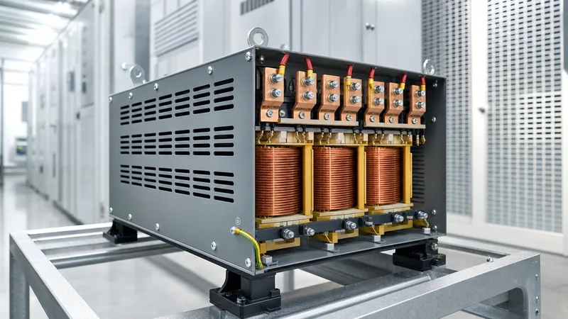
- Dry-Type Low Voltage Transformers: Operating with primary voltages up to 1 kV or 15 kV, these units use air as the cooling and insulating medium (cooling class AN or AF). Encapsulated in ventilated NEMA 1/3R or indoor ventilated enclosures, they are standard inside plant rooms due to their zero fire risk and absence of liquid containment needs.
- Miniature Liquid-Immersed Units: Typically rated from 25 kVA to 500 kVA, these transformers employ mineral oil, synthetic ester, or natural ester fluid. They are common in pole-mounted or pad-mounted rural electrification networks where environmental exposure requires hermetically sealed protection.
- Control and Industrial Isolation Transformers: Operating from 50 VA up to 10 kVA, these specialised units provide galvanic isolation for sensitive programmable logic controllers (PLCs), contactor coils, and instrumentation cabinets.
- Buck-Boost and Autotransformers: Compact magnetic assemblies engineered to adjust line voltage up or down by 5% to 20% without galvanic isolation, offering a cost-effective solution for voltage drop compensation.
Consulting our technical breakdown on the dry-type transformer guide offers additional perspective on resin-cast versus vacuum pressure impregnated (VPI) options within this power band.
Core Configurations and Winding Designs for Low Voltage Transformers
Core configurations and winding structures govern the efficiency, thermal footprint, and sound emissions of low voltage transformers in commercial and industrial settings. Designers select between stacked-lamination cores made of cold-rolled grain-oriented (CRGO) silicon steel or wound-core topologies, balancing eddy current mitigation with no-load losses (iron losses).
Winding conductors inside these units are constructed from high-conductivity electrolytic copper (Cu) or electrical-grade aluminium (Al). While copper delivers superior volumetric efficiency, smaller overall dimensions, and higher short-circuit mechanical strength, aluminium offers substantial weight reduction and thermal tolerance per unit mass. Insulation systems are rated according to temperature limits defined in IEC 60085, with Class F (155°C) and Class H (180°C) being standard for ventilated dry types, permitting average conductor rises of 80°C, 115°C, or 150°C above a 40°C ambient.
| Parameter | Single-Phase Small Unit | Three-Phase Low Voltage Unit | Cast Resin Industrial Unit |
|---|---|---|---|
| Typical Capacity Range | 5 kVA to 100 kVA | 15 kVA to 500 kVA | 50 kVA to 500 kVA |
| Standard Voltages (Primary) | 240 V / 480 V | 400 V / 480 V / 600 V | 3.3 kV / 6.6 kV / 11 kV |
| Standard Voltages (Secondary) | 120/240 V | 208Y/120 V, 400Y/230 V | 400Y/230 V, 480Y/277 V |
| Impedance (%Z at 75°C) | 1.8% – 3.5% | 2.8% – 5.5% | 4.0% – 6.0% |
| Typical Sound Level (NEMA/IEC) | 40 – 48 dB(A) | 45 – 55 dB(A) | 50 – 60 dB(A) |
| Common Cooling Method | AN (Air Natural) | AN or AF (Air Forced) | AN / AF (Class F/H) |
Electrical Sizing and Calculations for a Small Transformer
Electrical sizing for a small transformer requires calculating the total steady-state apparent power in kilovolt-amperes (kVA) while incorporating motor inrush currents, power factor, and anticipated spare capacity. Selecting an undersized unit leads to winding insulation degradation via thermal overload, while excessive oversizing increases capital expenditure and sustained no-load excitation losses.
To calculate the three-phase load capacity, apply the fundamental formula:
S = (V × I × √3) / 1000
Where S is apparent power in kVA, V is line-to-line voltage in Volts, and I is full-load continuous current in Amperes. For a facility running a continuous line current of 95 A on a 400 V three-phase system:
S = (400 × 95 × 1.732) / 1000 = 65.8 kVA
Factoring in a 25% continuous duty growth margin according to standard engineering practice yields 82.3 kVA. The engineer would select a standard 100 kVA commercial unit. You can model varied load steps using our transformer sizing calculator guide to automate multi-branch evaluations.
Short-circuit prospective current calculations are equally critical for downstream breaker coordination. The symmetrical fault current (Isc) delivered at secondary terminals is determined by:
Isc = Ifl / (Z% / 100)
Where Ifl represents full-load secondary current and Z% is the transformer nameplate impedance. On a 100 kVA, 400 V transformer with a 4.0% impedance, the full-load current is 144.3 A, resulting in a prospective short-circuit current of 144.3 / 0.04 = 3,608 A (3.61 kA), directly establishing the breaking capacity required for downstream protection gear.
Step-by-Step Procedure for Installing and Commissioning Small Transformers
Commissioning a small transformer requires systematic pre-energisation verification to ensure electrical integrity, correct winding insulation, and proper earthing. Field engineers and certified electricians must execute these five standard procedures before closing the supply breaker:
- Physical Inspection and Torque Verification: De-energise and lock out upstream feeds. Remove enclosure side panels to inspect for moisture, dust ingress, or shipping damage. Check all busbar connections and cable lugs using a calibrated torque wrench against manufacturer torque specifications (e.g., 45 Nm for standard M10 high-tensile copper bolts).
- Insulation Resistance (IR) Testing: Disconnect all neutral grounding straps and surge arresters. Using a calibrated 1000 V insulation tester, apply DC voltage for 60 seconds across primary-to-secondary, primary-to-ground, and secondary-to-ground windings. Minimum acceptable readings should exceed 100 MΩ at 20°C.
- Earthing and Bonding Confirmation: Verify that the transformer enclosure, neutral busbar (in solidly grounded Wye topologies), and core grounding strap form a continuous, low-impedance path to the primary substation ground ring, ensuring earth loop impedance measures under 1.0 Ω.
- Voltage Ratio and Polarity Verification: Inject a low-voltage test supply (e.g., 230 V single-phase) onto primary taps and measure secondary output across all phases to verify proper winding turn ratios and correct vector alignment (such as Dyn11 or DEn0).
- No-Load Energisation and Thermal Check: Energise the primary side without load. Verify secondary phase-to-phase and phase-to-neutral voltages with an industrial multimeter. Monitor for abnormal hum, vibration, or localized heating with an infrared camera over a two-hour dwell period prior to applying load circuits.
Efficiency Standards and Thermal Management in Low Voltage Applications
Efficiency standards for low voltage transformers are governed by mandatory international regulations designed to curb thermal dissipation and electrical waste across commercial grids. In North America, the Department of Energy standard 10 CFR Part 431 (DOE 2016) mandates minimum efficiency ratings between 97.0% and 99.2% for dry-type low voltage distribution units operating at 35% of nameplate load. In European territories, EN 50588-1 and the EU Ecodesign Directive enforce strict maximum allowable load and no-load losses.
Thermal management is intrinsic to transformer longevity. Winding thermal life obeys the Arrhenius rate law: every 8°C to 10°C increase above maximum insulation rating halves the service life of the dielectric paper, aramid paper, or epoxy resin. Engineers must evaluate whether standard convection (AN) cooling provides sufficient air displacement inside the room. Where equipment rooms exhibit restricted ventilation, installing forced air (AF) blowers with automated PT100 temperature controller integration increases continuous kVA capability by up to 25% to 33% without upsizing core iron.
Furthermore, when non-linear industrial loads (such as variable frequency drives, rectifiers, and switch-mode power units) populate the system, engineers must specify K-factor rated transformers (e.g., K-4, K-13, or K-20). Standard transformers overheat rapidly under non-sinusoidal harmonic load currents because eddy current losses scale with the square of the harmonic frequency.
Next steps: specifying and sourcing
When preparing an inquiry or technical tender for a small transformer or low voltage distribution project, providing precise site criteria ensures optimal design and rapid factory turnaround. Ensure your engineering requisition details continuous kVA capacity, primary and secondary voltage configurations, vector group, insulation temperature class, impedance limits, and required enclosure protection (IP or NEMA rating). For challenging environments, review our factory-built dry-type transformers and outdoor-ready oil-immersed transformers. For tailored technical proposals and commercial bids, reach out directly to our engineering team through our dedicated quote page.
Frequently asked questions
What is considered a small transformer?
A small transformer is generally defined as an electrical unit rated from 5 kVA up to 500 kVA, operating at low or medium distribution voltages. These units step down supply voltages for secondary building circuits, industrial machinery, and local control equipment.
What is the difference between small power transformers and low voltage transformers?
Small power transformers typically refer to any unit handling moderate kVA capacity, including medium-voltage primaries, whereas low voltage transformers specifically operate with both primary and secondary windings rated at or below 1,000 V AC.
Can a small transformer be run in reverse to step up voltage?
Yes, standard small transformers can be back-fed to step up voltage if installed in accordance with electrical codes. However, excitation inrush current will be substantially higher, requiring appropriately sized upstream circuit protection to prevent nuisance tripping.
What maintenance is required for dry-type small transformers?
Maintenance for dry-type small transformers involves periodic visual inspections, thermal imaging under load, de-energised cleaning of ventilation louvres to remove dust, checking terminal bolt torques, and annual insulation resistance testing to verify winding dielectric health.
Why do low voltage transformers hum during operation?
Low voltage transformers hum primarily due to magnetostriction, where magnetic flux causes the laminated silicon steel core sheets to mechanically expand and contract at twice the power frequency. Loose enclosure panels or resonant mounting surfaces can amplify this acoustic noise.
Tags: small transformer low voltage transformers dry type transformer distribution transformer transformer sizing


