Key takeaways
- A dry type transformer relies on ambient air circulation or solid resin encapsulation rather than dielectric fluid for core and winding insulation.
- Cast resin transformers (CRT) achieve the highest mechanical withstand and moisture resistance with partial discharge levels below 10 picocoulombs (pC).
- Vacuum pressure impregnated (VPI) units offer excellent thermal flexibility up to Class H (180°C) and Class C (220°C) at a lower initial capital cost.
- IEC 60076-11 defines stringent climatic, environmental, and fire behaviour classifications (C2, E2, F1) essential for indoor infrastructure.
- Forced-air ventilation (AF) can increase continuous transformer throughput by 25% to 40% above the natural convection (AN) nominal rating.
Quick answer: A dry type transformer is an electrical transformer whose magnetic core and copper or aluminium windings are insulated and cooled by air or solid insulating resins, completely eliminating flammable dielectric liquid. Commonly specified between 100 kVA and 25,000 kVA for voltages up to 36 kV, it provides safe, zero-fire-risk power distribution inside high-occupancy commercial and industrial buildings.
As industrial plants, commercial towers, datacentres, and transport infrastructures push medium-voltage distribution deeper into building cores, the risks associated with mineral-oil-filled equipment become unacceptable. Oil-immersed units require external blast walls, fire-deluge systems, and oil-containment sumps to satisfy local building codes such as NFPA 70 (National Electrical Code) and regional building regulations. In contrast, modern solid-insulation units can be co-located directly adjacent to medium-voltage switchgear and low-voltage switchboards, reducing cable runs and cutting transmission line losses.
Selecting the optimal transformer involves navigating distinct insulation systems, thermal endurance classes, harmonic load factors, and environmental durability ratings. Whether evaluating a standard cast resin unit or a high-temperature open-wound design, project engineers must balance initial capital expenditure with operational efficiency, total cost of ownership, and stringent compliance with IEC 60076-11 or IEEE C57.12.01 standards.
What is a dry type transformer and how does it work?
A dry type transformer operates by transferring electrical energy between voltage levels via electromagnetic induction while dissipating its internal heat losses directly into the surrounding atmosphere without liquid cooling media. Unlike liquid-immersed units where oil acts as both a primary dielectric insulator and thermal transfer agent, dry units use gaseous air, solid epoxy resin, or high-temperature synthetic wraps to prevent electrical breakdown across internal clearances.
The physical construction comprises high-permeability, cold-rolled grain-oriented (CRGO) silicon steel laminations stacked to form the magnetic core. The high-voltage (HV) and low-voltage (LV) windings are wound concentrically around the core limbs. Detailed insights into core geometry and core loss mitigation are explored in our guide to transformers internal components. When an alternating medium voltage is applied across the primary winding, it induces a dynamic magnetic flux within the core, which in turn induces a secondary voltage in the low-voltage winding proportional to the turns ratio:
V1 / V2 = N1 / N2 = I2 / I1
Thermal dissipation in a dry transformer occurs through two distinct natural mechanisms: thermal conduction through the solid dielectric insulation to the winding surface, followed by natural convection and radiation off the winding faces into the surrounding ambient air. Because air has a significantly lower thermal conductivity (approximately 0.026 W/m·K) than mineral oil (approx. 0.13 W/m·K), dry type units are physically larger and incorporate dedicated cooling ducts cast directly into the winding structure to facilitate rapid convective air draughts.
Major dry type transformer types: Cast resin vs VPI vs VPE
The market categorises dry type transformer types by their winding encapsulation technique: Cast Resin (CRT), Vacuum Pressure Impregnated (VPI), and Vacuum Pressure Encapsulated (VPE). Each manufacturing methodology provides distinct operational advantages depending on ambient atmospheric conditions, presence of airborne contaminants, and short-circuit mechanical requirements.
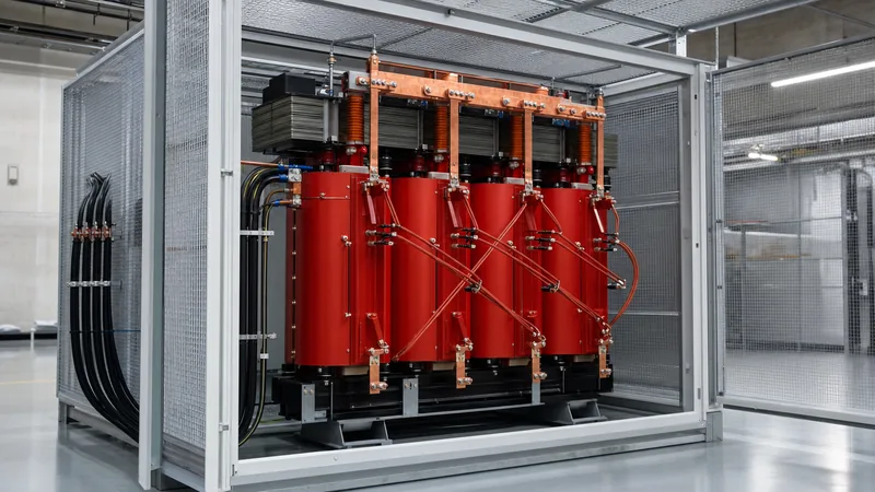
Cast Resin Dry Type (CRT) units feature high-voltage windings fully encapsulated in epoxy resin mixed with silica filler under a high vacuum. This eliminates air voids within the insulation matrix, resulting in exceptional partial discharge performance (typically below 10 pC at 1.3 times rated phase-to-ground voltage). The monolithic resin shell forms a hermetic seal impervious to moisture, chemical fumes, and heavy industrial dust, making CRT the preferred choice for commercial basements, tunnels, offshore platforms, and coastal substations.
Vacuum Pressure Impregnated (VPI) units employ high-temperature Class H or Class C materials (such as aramid paper) wound around the conductors, preheated, and then submerged in a polyester or silicone varnish tank under vacuum and pressure cycles. The varnish thoroughly penetrates the inter-turn paper insulation but leaves the outer surface unencapsulated. VPI designs provide superior resistance to thermal cycling stresses, handle high-overload currents without thermal cracking, and weigh less than CRT units, making them the standard for clean industrial manufacturing floors and datacentres.
Vacuum Pressure Encapsulated (VPE) designs use an enhanced multi-dip silicone resin system that cures into a thicker protective skin than standard VPI. VPE bridges the gap between open-wound VPI and cast resin, offering moderate environmental protection in moist or mildly corrosive environments without the extreme mass of solid epoxy.
| Parameter / Feature | Cast Resin (CRT) | Vacuum Pressure Impregnated (VPI) | Vacuum Pressure Encapsulated (VPE) |
|---|---|---|---|
| HV Winding Insulation | Solid epoxy resin with quartz filler | Aramid paper impregnated with polyester varnish | Aramid wrap with heavy silicone elastomer cure |
| Thermal Insulation Class | Class F (155°C) or Class H (180°C) | Class H (180°C) or Class C (220°C) | Class H (180°C) or Class C (220°C) |
| Partial Discharge (PD) | < 5 to 10 pC (Extremely low) | Not typically specified (> 50 pC) | Moderate (20 to 40 pC) |
| Moisture & Dust Resistance | Exceptional (Immune to humidity) | Moderate (Requires climate control) | |
| Short-Circuit Withstand | Superior (Rigid monolithic structure) | Moderate to High | High |
| Repairability | Requires coil replacement | Field varnish repair possible | Field varnish repair possible |
| Relative Cost | Baseline (+15% to +25% vs VPI) | Most economical | Moderate (+10% vs VPI) |
Insulation classes and thermal performance standards
Thermal insulation endurance classes govern the operational lifespan of a dry type transformer by establishing the maximum continuous permissible temperature under rated loading. Standardised across IEC 60076-11 and IEEE C57.12.01, insulation systems are classified into temperature thresholds: Class B (130°C), Class F (155°C), Class H (180°C), and Class C (220°C).
The thermal rating represents the sum of three distinct thermal components: the maximum reference ambient temperature (standardised at 40°C), the average winding temperature rise under full load measured by electrical resistance, and a safety margin for the inner core-to-winding hot spot. For instance, a standard Class F cast resin transformer is engineered for a maximum winding temperature rise of 100 K (Kelvin) above a 40°C ambient, leaving a 15 K hot-spot allowance before reaching the 155°C ultimate breakdown limit.
Specifying a transformer with an insulation class higher than its rated temperature rise yields substantial thermal headroom. A common engineering strategy is to specify a Class H (180°C) insulation system while constraining the design to a Class F (100 K) temperature rise. According to the Arrhenius thermal ageing relationship, operating a solid dielectric insulation system 10°C below its thermal class limit roughly doubles its mechanical insulation lifespan:
L = L0 × 2(Tmax - Top) / 10
Where L is actual thermal lifetime, L0 is rated design life, Tmax is maximum thermal limit, and Top is actual winding hot-spot operating temperature. This conservative thermal buffer allows the unit to tolerate unexpected sustained overloads or ambient HVAC disruptions without accelerating dielectric embrittlement.
Specifying a dry type distribution transformer for commercial and industrial facilities
Correctly sizing a dry type distribution transformer requires calculating the exact continuous kVA load profile, establishing the incoming medium-voltage rating, selecting an appropriate vector group, and accounting for non-linear harmonic heating. System planners must assess both continuous operating demands and dynamic motor-starting inrush currents, cross-referencing values with our transformer sizing calculator guide.
Standard primary distribution voltages include 11 kV, 22 kV, and 33 kV at 50 Hz, or 4.16 kV, 12.47 kV, and 13.8 kV at 60 Hz. The secondary voltage is typically 400 V or 415 V three-phase four-wire (with a solid neutral) for European and Commonwealth systems, or 480Y/277 V and 208Y/120 V for North American infrastructure. The most universally applied distribution vector configuration is Dyn11, where the high-voltage winding is connected in Delta and the low-voltage in Star with a neutral point, offering a 30-degree lead angle that traps zero-sequence triplen harmonics inside the Delta mesh; comprehensive details are documented in our review of transformer vector groups.
When specifying equipment destined for commercial datacentres or industrial facilities running variable speed drives (VSDs), switch-mode power supplies, and uninterruptible power systems (UPS), non-linear harmonic currents induce severe eddy-current and stray load losses in the windings. In such applications, an off-the-shelf unit will rapidly overheat. Specifiers must calculate the overall harmonic load factor and specify a K-factor rated unit per IEEE C57.110:
K = ∑ [ Ih2 × h2 ] / ∑ [ Ih2 ]
A standard distribution unit possesses a rating of K-1. Installations supplying 50% to 100% non-linear loads require K-4, K-13, or K-20 ratings, which incorporate multi-strand transposed conductors to minimise skin effect and heavy neutral busbars rated at 200% of phase current to accommodate additive triplen harmonics.
Enclosure IP ratings, cooling methods, and forced ventilation
A dry type transformer relies directly on its protective enclosure to balance mechanical ingress resistance with free-flowing convective cooling. Enclosures are classified under the international Ingress Protection (IP) code defined by IEC 60529 or NEMA standards defined by NEMA 250.
The standard baseline configuration is IP00, denoting an unhoused, bare core-and-coil assembly engineered strictly for installation inside a locked, climate-controlled medium-voltage switchgear lineup or containerised plant room. When deployed as a standalone indoor unit, the baseline standard is IP21, which provides ingress protection against solid objects larger than 12.5 mm (preventing accidental finger contact with energized terminals) and protects against vertically falling drops of water. For harsher facilities exposed to indoor washdowns, wind-driven moisture, or industrial mist, IP23 (angled water spray up to 60°) or IP31 (solids down to 2.5 mm) is specified.
Cooling modes are fundamentally designated as Air Natural (AN) or Air Forced (AF):
- AN (Air Natural): The transformer relies entirely on natural buoyancy-driven convection through winding ducts and ambient thermal dissipation through enclosure louvres.
- AF (Air Forced): Cross-flow tangential cooling blowers mounted below the core limbs blow chilled air directly into the inner coil channels upon signal from embedded PT100 temperature sensors.
Activating forced-air cooling blowers increases the continuous heat-dissipation throughput, allowing an AN-rated unit to operate continuously at an AF rating up to 133% to 140% of its base kVA nameplate. For example, a 2000 kVA AN dry-type transformer can safely support a continuous 2660 kVA demand during peak loading cycles under AF operation, eliminating the need to physically oversize the steel core.
Testing, commissioning, and maintenance procedures
Verifying the mechanical integrity and dielectric strength of a newly installed dry type transformer requires systematic factory acceptance testing followed by rigorous field pre-commissioning checks. Skipping these diagnostic steps risks catastrophic flashovers during initial energisation under system line voltage.
The field commissioning sequence should be executed in a strict chronological order:
- Visual Inspection and Cleaning: Inspect all resin castings or varnish impregnations for micro-fissures, shipping transit fractures, or debris accumulation; vacuum clean all convective cooling ducts and wipe winding surfaces with lint-free solvent cloths.
- Insulation Resistance (IR) Testing: Apply a calibrated direct-current (DC) test voltage using a megohmmeter (typically 2.5 kV or 5 kV DC for HV windings, 1 kV DC for LV windings) for 60 seconds; verify minimum insulation values conform to IEEE 43 and factory test baselines.
- Winding Resistance Measurement: Measure direct current resistance across all winding phase pairs (HV and LV) using a micro-ohmmeter to ensure balance within ±1% across phases, confirming terminal tightness and tap-changer contact pressure.
- Voltage Ratio and Vector Group Verification: Apply a low-voltage three-phase excitation source to verify turns ratio accuracy across all tap positions within the ±0.5% tolerance limit specified by IEC 60076-1.
- Dielectric Withstand / Applied Voltage Testing: Conduct power-frequency high-potential (Hi-Pot) testing at 75% to 80% of original factory test voltage values to confirm insulation integrity without overstressing aged components.
- Temperature Sensor Loop Check: Calibrate and functional-test embedded resistance temperature detectors (Pt100 sensors) across core limbs and winding phases, ensuring trip and alarm threshold interlocks actuate cooling fans and upstream circuit-breaker shunts accurately.
Before signing off on plant delivery, ensure all baseline parameters match the metrics documented on the transformer factory acceptance testing checklist.
Evaluating dry type transformer manufacturers and technical supplier criteria
Procuring reliable power equipment requires evaluating dry type transformer manufacturers on verifiable manufacturing capabilities, certified test evidence, and core material sourcing rather than purchase price alone. A qualified dry type transformer supplier must hold active ISO 9001, ISO 14001, and ISO 45001 accreditations, alongside comprehensive type test reports issued by independent, internationally accredited laboratories such as KEMA, CESI, or UL.
When auditing factory production capabilities, consulting engineers must scrutinise three critical areas:
- Resin Casting and Impregnation Infrastructure: For cast resin designs, confirm the supplier utilizes computer-controlled differential vacuum casting chambers with automatic degassing to eliminate microscopic voids; inspect resin mixing ratios and silica filler dispersion controls.
- Partial Discharge Testing Protocols: Every manufactured unit must undergo routine partial discharge testing in a shielded Faraday room. Ensure the supplier guarantees partial discharge levels < 10 pC at 1.30 or 1.44 Um / √3 per IEC 60076-11 Clause 14.3.2.
- Core Cutting and Step-Lap Assembly: Inquire whether the manufacturer cuts CRGO laminations in-house using computerized automated step-lap slitting lines, which drastically reduces core gap reluctance, exciting currents, and audible noise.
Furthermore, ensure the supplier provides environmental, climatic, and fire behaviour certificates verifying class ratings: E2 (heavy condensation and severe pollution), C2 (operation down to -25°C), and F1 (fire risk mitigation with self-extinguishing resin that releases zero toxic halogens during external combustion).
Total cost of ownership: Dry transformer vs liquid-filled alternatives
Evaluating the total cost of ownership (TCO) between a dry transformer and an oil-immersed equivalent requires factoring civil installation costs, environmental risks, maintenance overhead, and capital depreciation over a 25- to 30-year design life. While a cast resin dry-type unit typically incurs a 20% to 35% higher initial purchase price than a mineral-oil-filled transformer of identical kVA rating, it frequently delivers a lower total lifetime project cost for indoor applications.
The economic differential is driven primarily by indoor civil works and safety infrastructure. Liquid-immersed transformers installed inside a facility mandate fire-rated concrete vault walls, outdoor proximity clearances, oil capture containment pits, sump pumps with oil-water separators, and automated clean agent or deluge firefighting equipment. A dry type unit requires none of these civil containment systems, freeing up floor space and reducing mechanical contractor scope. An in-depth comparison of these physical and financial trade-offs can be found in our guide comparing oil-immersed vs dry-type transformers.
Operational maintenance for dry type units is virtually zero compared to liquid equipment. Oil-immersed units require recurring dielectric fluid sampling, dissolved gas analysis (DGA), moisture testing, bushing re-gasketing, and periodic oil filtration. Dry type units require only routine visual checks, thermal infrared scanning of connection lugs, and periodic vacuum cleaning of cooling pathways during scheduled plant shutdowns. When combined with substantial reductions in building fire insurance premiums, the initial purchase premium of a dry-type unit is typically amortised within three to five years of operational service.
Next steps: specifying and sourcing
When preparing a formal Request for Quotation (RFQ) for your project, ensure your engineering schedules include exact system parameters: primary and secondary voltages, BIL impulse withstand levels, vector group, impedance (%Z), enclosure IP rating, K-factor requirements, and environmental classifications (such as E2, C2, F1). Our engineering team designs and manufactures standard and custom dry type distribution transformers, vacuum pressure impregnated units, and integrated medium-voltage packages built to IEC 60076 and IEEE C57 standards.
To evaluate our robust medium-voltage equipment offerings, explore our high-efficiency dry-type transformer range, examine matching HV and LV switchgear lineups, or review our integrated outdoor transformer substation solutions. When your design parameters are established, submit your single-line diagrams directly to our engineering team through our transformer quotation page for detailed submittals, full loss performance calculations, and competitive project pricing.
Frequently asked questions
What is the primary difference between cast resin and VPI dry type transformers?
Cast resin transformers feature coils completely encapsulated in solid epoxy resin under vacuum, offering total moisture immunity and partial discharge below 10 pC. Vacuum pressure impregnated (VPI) units use aramid paper wound coils saturated in varnish, providing superior thermal cycling resistance up to Class C (220°C) at a lower weight.
Can a dry type transformer be installed outdoors?
Yes, a dry type transformer can be installed outdoors if it is housed inside a weatherproof, environmentally sealed enclosure rated IP44, IP54, or NEMA 3R/4. However, the enclosure must be engineered with filtered air louvres, space heaters to prevent internal condensation, or air-to-air heat exchangers.
What is the typical lifespan of a dry type transformer?
A high-quality dry type transformer operating within its rated thermal design limits typically achieves a lifespan of 25 to 30 years. Specifying a higher thermal insulation class (such as Class H) with a lower actual operating temperature rise (Class F) can extend operating life to 35 years or more.
What causes partial discharge in cast resin dry type transformers?
Partial discharge is caused by localized electrical stress exceeding the dielectric breakdown strength of microscopic air voids trapped within the epoxy resin matrix. Reputable manufacturers use automated differential vacuum degassing and dynamic mould casting to eliminate internal voids, maintaining partial discharge below 10 picocoulombs (pC).
How does forced-air (AF) cooling affect transformer capacity?
Forced-air (AF) cooling utilizes cross-flow ventilation fans to increase the continuous output capacity of a naturally cooled (AN) transformer by 25% to 40%. For example, an air-natural unit rated at 1000 kVA can continuously support 1330 kVA to 1400 kVA when cooling fans are engaged.
Why are dry type transformers preferred for indoor applications?
Dry type transformers eliminate flammable mineral oil, significantly reducing fire and explosion hazards in indoor environments. This eliminates the necessity for concrete blast containment vaults, oil collection pits, and active fire suppression systems, satisfying strict municipal building codes and insurance standards.
Tags: dry type transformer dry type transformer types dry transformer dry type distribution transformer dry type transformer manufacturers dry type transformer supplier