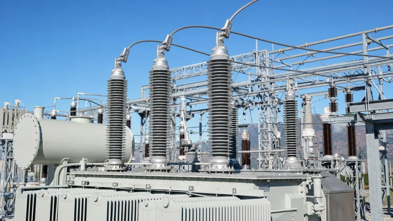
Key takeaways
- A transformer bushing provides an insulated conductive pathway allowing high-voltage conductors to pass safely through an earthed transformer tank wall.
- Condenser bushings manage high radial and axial dielectric stress using concentric capacitive layers interleaved with paper or synthetic film.
- Resin impregnated paper (RIP) and resin impregnated synthetic (RIS) technologies eliminate oil leakage risks and explosion hazards compared to traditional oil impregnated paper (OIP).
- Routine field diagnostic testing per IEEE C57.19.00 relies on power factor (tan delta) and capacitance measurements across the C1 core and C2 tap insulation.
- Creepage distance must be specified according to IEC 60815 pollution severity classes, typically requiring 25 mm/kV to 31 mm/kV for moderate to severe industrial environments.
Quick answer: A transformer bushing is an insulated structural component that enables an energised electrical conductor to pass safely through the grounded metallic tank of a transformer without flashing over or degrading system insulation. It provides mechanical support, hermetic sealing against oil leakage or moisture ingress, and precise capacitive voltage grading along its axial length.
In alternating-current power systems, the interface between the internal winding leads and the external transmission network represents one of the highest dielectric stress regions in substation engineering. A failure at this junction frequently leads to catastrophic explosive rupture, collateral equipment fires, and extended substation outages. Understanding the operational physics, thermal dissipation requirements, and mechanical loading limits of an electrical bushing is fundamental to specifying dependable equipment across distribution networks and transmission substations.
Modern power grids subject a large power transformer to dynamic system disturbances, including steep-front lightning surges, switching transients, and temporary overvoltages. Selecting the appropriate insulation topology, whether unbonded non-condenser types for medium-voltage switchgear interfaces or graded condenser arrangements for high-voltage transmission apparatus, directly determines the asset lifecycle. This guide details technical architectures, diagnostic limits, and selection criteria essential for electrical engineers and procurement specialists.
What Is a Transformer Bushing and How Does It Function?
A transformer bushing is an insulated hollow structure that routes high-voltage conductors into an earthed enclosure while controlling both axial and radial electrical field stress. Without a specialized insulating barrier, the electric field between an energised line terminal and the grounded transformer lid would exceed the dielectric breakdown strength of ambient air, triggering immediate flashover.
The assembly must simultaneously withstand mechanical strain imposed by incoming overhead line spans, seismic accelerations, and electromagnetic forces generated during downstream short-circuit faults. Concurrently, it maintains a gas-tight and fluid-tight barrier, preventing insulating liquid or insulating gas from leaking out of the tank while blocking ambient moisture from entering the dielectric medium. For comprehensive network architectures, coordinating terminal insulation directly impacts overall transformer protection schemes across primary plant.
Internally, the conductor may consist of a solid copper draw-rod, a hollow aluminium or copper tube serving as a draw-lead carrier, or a cast copper terminal stud designed for heavy current loading. As voltage levels exceed 36 kV, non-graded geometric insulation becomes prohibitively bulky. Consequently, engineered dielectric cores divide the total potential difference into predictable, manageable increments from the centre conductor to the earthed flange.
Non-Condenser vs Condenser Bushing Construction
Non-condenser bushings rely strictly on the bulk thickness and geometric clearance of an insulating material, whereas condenser bushings incorporate calculated capacitive grading layers to distribute dielectric stresses uniformly.
In a non-condenser design, typically employed up to 36 kV or 52 kV, the primary insulation consists of solid porcelain, cast epoxy resin, or polymeric compounds surrounding the central conductor. Because there is no internal capacitive control, the electric field intensity is highest at the outer surface of the conductor and drops off steeply toward the grounded mounting flange. As nominal system voltages increase, the diameter and clearances of non-condenser insulators grow exponentially, rendering them impractical for transmission apparatus.
A modern power transformer bushing designed for high-voltage operation utilizes a condenser core. This condenser core consists of coaxial conducting or semi-conducting cylinders embedded within an insulating matrix. By balancing the surface area and radial separation of these conductive foils, design engineers create a series chain of equal capacitances. According to fundamental capacitive divider theory:
Vn = Vtotal × (1 / Cn) / ∑(1 / Ci)
Because each capacitive section retains equal capacitance, the potential distributes linearly from the line-potential core to the grounded mounting flange. This design flattens internal radial stress and axial surface stress, dramatically shrinking the external physical dimensions required to withstand lightning impulse voltages and power-frequency testing.
Insulation Technologies: OIP, RIP, and RIS High Voltage Transformer Bushings
High-voltage condenser bushings are predominantly classified by their internal dielectric media, namely Oil Impregnated Paper (OIP), Resin Impregnated Paper (RIP), and Resin Impregnated Synthetic (RIS) designs.
Historically, Oil Impregnated Paper served as the global standard for any high voltage bushing. An OIP core is wound using kraft paper with inserted aluminium foils, vacuum-dried, impregnated with degassed mineral insulating oil, and hermetically sealed inside an outer porcelain housing. While displaying proven dielectric longevity and low initial capital expenditure, OIP units contain combustible fluid under pressure. An internal partial discharge event or thermal breakdown can generate combustible gases, sparking explosive shattering of the external porcelain and scattering shrapnel across adjacent substation assets.
Resin Impregnated Paper technology eliminates free oil. An RIP core is wound using high-purity crepe paper interleaved with capacitive foils, then impregnated under vacuum with an epoxy resin matrix and cured thermally. The resulting core is a solid, dry composite body that can be equipped with either an external porcelain housing or a directly moulded silicone composite weather-shed. In catastrophic internal electrical failure, RIP designs do not catch fire or explode into ballistic fragments, substantially improving worker safety and fire containment.
Resin Impregnated Synthetic technology advances the dry concept further by replacing hygroscopic cellulose paper with a synthetic non-woven polyester or polymer fabric. Because synthetic fabrics do not absorb atmospheric moisture during factory assembly or storage, RIS high voltage transformer bushings eliminate paper aging and moisture ingress risks altogether. RIS units exhibit exceptional dielectric dissipation factor stability, maintaining partial discharge levels below 2 pC even under severe thermal cyclic duty.
Technical Comparison of Modern Electrical Bushing Types
The choice between solid, liquid-filled, and dry condenser designs depends on system voltage, seismic exposure, environmental pollution, and lifecycle maintenance priorities.
| Parameter | Solid Non-Condenser (Porcelain/Resin) | Oil Impregnated Paper (OIP) | Resin Impregnated Paper (RIP) | Resin Impregnated Synthetic (RIS) |
|---|---|---|---|---|
| Voltage Class Range | Up to 52 kV | 24 kV to 1,100 kV | 24 kV to 800 kV | 24 kV to 550 kV |
| Dielectric Loss (tan δ) | 0.010 – 0.030 | 0.002 – 0.004 | 0.003 – 0.005 | 0.003 – 0.004 |
| Fire & Explosion Hazard | Negligible | High (flammable oil) | Extremely Low (dry core) | None (explosion-resistant) |
| Moisture Sensitivity | Low | Low (hermetic) | Moderate (prior to assembly) | Negligible (hydrophobic fabric) |
| Mounting Angle Limit | Any orientation | Max 30° from vertical | Any orientation (0°–90°) | Any orientation (0°–90°) |
| Maintenance Demand | Visual only | Oil level, DGA, DDF | DDF, capacitance checks | Minimal periodic testing |
| Typical Standards | IEC 60137 / IEEE C57.19.00 | IEC 60137 / IEEE C57.19.01 | IEC 60137 / IEEE C57.19.01 | IEC 60137 / IEEE C57.19.01 |
As documented in modern utility specifications, utilities transitioning away from OIP are increasingly standardising on composite-housed RIP and RIS architectures for high-criticality assets connected to transmission grid substations.
Key Design Criteria: Creepage, BIL, and Thermal Sizing
Specifying a power transformer bushing demands rigorous coordination of environmental pollution exposure, transient impulse withstand levels, and continuous thermal current handling.
Creepage distance represents the shortest pathway along the outer insulating surface between the energised terminal and the earthed flange. Outdoor air contaminants, such as maritime salt spray, desert dust, or industrial chemical particulates, settle on weather-shed surfaces. When wetted by light rain or fog, these deposits form conductive films that incite leakage currents, partial arcing, and ultimately external flashover. Engineers must align minimum specific creepage distances with IEC 60815 pollution severity classes:
- Class a (Very Light): 22 mm/kV (phase-to-ground equivalent).
- Class b (Light): 28 mm/kV.
- Class c (Medium): 35 mm/kV.
- Class d (Heavy): 43 mm/kV.
- Class e (Very Heavy): 54 mm/kV.
Basic Impulse Insulation Level (BIL) defines an insulator's capability to withstand lightning transients and steep-front overvoltages without dielectric puncture. Per IEC 60076-3 and IEEE C57.12.00 Table 5, a 145 kV class equipment installation requires a minimum lightning impulse withstand of 650 kV peak and a power-frequency withstand voltage of 275 kV rms. Bushing insulation must provide a safety margin over internal winding insulation levels to ensure surge arresters clamp incoming waves before external breakdown occurs.
Thermal sizing requires verifying continuous rated current (Ir) alongside dynamic short-time withstand current (Ith). Because winding leads produce localized resistive heating, conductor sizing must limit temperature rise inside the condenser core. Under IEC 60137 clause 8.1, maximum top-flange connection temperatures must not exceed 105°C for standard copper alloys under full rated loading.
Worked Engineering Calculation: Capacitive Voltage Gradient
To understand electric stress distribution within a high-voltage condenser core, engineers calculate the radial electric field across successive capacitor foils. Consider a 145 kV class RIP condenser bushing operating at maximum system phase-to-ground voltage:
Vph-g = 145 kV / √3 ≈ 83.72 kV rms (118.4 kV peak)
The condenser core is engineered with 20 capacitive aluminium grading layers (N = 20) positioned between the inner conductor tube of outer radius r0 = 25 mm and the grounded outer layer at radius r20 = 65 mm.
The design balances foil lengths such that each capacitive element exhibits an identical capacitance of C = 400 pF. The voltage dropped across each intermediate capacitive section is uniform:
ΔV = Vph-g / N = 83.72 kV / 20 = 4.186 kV rms per layer
The radial electric field E at any radius r within an individual dielectric layer between conductive cylinders ri and ri+1 is governed by the cylindrical electrostatics equation:
E(r) = ΔV / [r × ln(ri+1 / ri)]
For the innermost layer, where r0 = 25.0 mm and r1 = 26.5 mm:
ln(26.5 / 25.0) = ln(1.06) ≈ 0.05827
E(r0) = 4,186 V / [0.025 m × 0.05827] ≈ 2,873,500 V/m = 2.87 kV/mm
Because the breakdown threshold of resin-impregnated paper typically exceeds 35 kV/mm under power frequency conditions, an operating gradient of 2.87 kV/mm provides a safe dielectric safety factor exceeding 12:1. This calculation confirms that uniform capacitive grading suppresses dangerous electrical stress peaks, preserving component longevity over decades of continuous energisation.
Factory and Field Testing Procedures for Electrical Bushings
Electrical bushing integrity must be validated via rigorous dielectric and thermal evaluations prior to factory dispatch and routinely verified during plant commissioning per established transformer testing procedures.
The primary non-destructive diagnostic benchmark in the field is the Dissipation Factor (tan δ) and Capacitance measurement. Condenser designs incorporate a test tap or voltage tap connected directly to the outermost condenser foil. Using high-voltage bridge instruments, engineers measure two critical parameters:
- Main Core Insulation (C1): Measured between the central conductor and the test tap, with the mounting flange solidly earthed. This evaluates the overall bulk dielectric core.
- Tap Insulation (C2): Measured between the test tap and the grounded mounting flange, evaluating the final protective insulating layer and weather-seal integrity.
IEEE C57.19.00 specifies that for new OIP units, the power factor at 20°C should remain below 0.5%, whereas modern RIP and RIS units must maintain dissipation factors below 0.4%. An increase in measured C1 capacitance exceeding 5% indicates that internal capacitive layers have shorted through puncture breakdown. An increase in tan δ signifies moisture ingress, resin degradation, or thermal oil oxidation.
Factory acceptance testing further requires Partial Discharge (PD) testing under IEC 60270. During induced voltage testing at 1.5 times maximum phase-to-ground voltage, background partial discharge must not exceed 5 pC for RIP or RIS apparatus, and 10 pC for OIP apparatus. Higher discharges denote micro-voids, delamination of paper layers, or incomplete vacuum impregnation.
Procurement and Engineering Checklist for Bushings
Procuring replacement units or specifying high-voltage terminals for new transformer assets requires exact matching of dimensional, electrical, and thermal interfaces.
Before issuing a Request for Quotation (RFQ), ensure the following engineering parameters are fully established:
- System Operating Voltage and BIL: Highest system voltage (Um), rated power-frequency withstand, and full-wave lightning impulse peak rating.
- Continuous and Dynamic Currents: Rated continuous current (Ir) considering ambient operating temperature, altitude derating above 1,000 metres, and symmetrical short-circuit current withstand (Ith for 1 to 3 seconds).
- Mounting Geometry: Tank hole diameter, bolt pitch circle diameter (PCD), number and size of studs, flange thickness, and maximum permissible immersion depth below the tank cover.
- Connection Interface: Draw-rod versus fixed conductor, terminal stud threading (metric vs NEMA spade flat-pad connectors), and current transformer (CT) pocket clearance length.
- Insulation Housing Material: Glazed brown/grey porcelain or hydrophobic silicone rubber composite sheds, defined by the site-specific IEC 60815 pollution severity level.
- Diagnostic Provisions: Test tap for offline tan δ verification or specialized self-grounding voltage tap compatible with continuous online bushing monitoring systems.
Next Steps: Specifying and Sourcing
When preparing specifications for custom high-voltage terminals or procuring fully assembled apparatus, precise coordination between transformer active parts, current transformer pocket clearances, and external connection hardware prevents costly plant delays. Review our engineered power transformer solutions and explore heavy-duty oil-immersed transformer units tailored to international utility standards.
Send your dimensional drawings, required BIL levels, creepage metrics, and current ratings directly to our application engineering department. Request a competitive, factory-direct quotation via our transformer quotation page, or connect with our technical sales division at our engineering contact portal to ensure your primary substation assets operate with dependable electrical insulation.
Frequently asked questions
What is the purpose of a transformer bushing?
A transformer bushing provides an insulated path that allows a high-voltage conductor to pass through an earthed transformer tank without flashing over. It controls radial and axial electric field stress while mechanically supporting terminal connections and sealing the internal insulating medium.
What is the difference between OIP and RIP bushings?
OIP (Oil Impregnated Paper) uses paper insulation saturated with mineral oil inside a sealed porcelain housing, posing fire and explosion risks if punctured. RIP (Resin Impregnated Paper) uses a solid resin-impregnated paper core that is entirely dry, eliminating fire hazards and permitting mounting at any angle.
What causes a transformer bushing to fail?
Bushing failures typically result from moisture ingress past degraded elastomeric gaskets, thermal aging of cellulose, or high partial discharges causing dielectric breakdown across capacitive grading layers. These failure mechanisms often lead to internal arcing, shorted foils, and explosive structural rupture.
What does a high tan delta value indicate in a bushing?
A high tan delta (dielectric dissipation factor) indicates increased dielectric losses caused by moisture contamination, chemical degradation of the insulating resin or oil, or localized carbon tracking. A significant upward trend indicates that the insulation is deteriorating and approaching dielectric breakdown.
How often should transformer bushings be tested in the field?
High-voltage transformer bushings should undergo visual inspection and thermographic scanning annually, with comprehensive offline capacitance and tan delta (C1 and C2) measurements conducted every three to five years. Assets in critical grid transmission nodes are frequently equipped with online monitoring sensors for continuous real-time diagnosis.
Tags: transformer bushing electrical bushing power transformer bushing high voltage bushing high voltage transformer bushings


