Key takeaways
- Vista switchgear integrates vacuum interrupters and visible disconnects within a sealed, submersible enclosure rated up to 38 kV.
- Underground distribution switchgear eliminates exposed live medium-voltage conductors using IEEE 386 deadfront bushing interfaces.
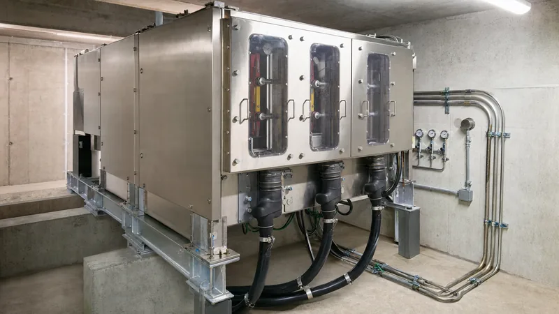
- Integrated viewing windows allow operators to visually verify open gaps without breaching the hermetically sealed gas or dielectric chamber.
- Fault-interrupting ratings typically span 12.5 kA to 25 kA symmetrical at operating voltages of 15.5 kV, 27 kV, and 38 kV.
- Automated underground switchgear units incorporate microprocessor relays and motor operators for self-healing loop and microgrid configurations.
Quick answer: Vista switchgear is a factory-assembled, medium-voltage underground distribution switchgear system designed for vault or pad-mounted service up to 38 kV. It combines load-break switches and vacuum fault interrupters sealed within a submersible, corrosion-resistant tank, providing elbow-connected deadfront termination, visible isolation gaps through observation windows, and automated overcurrent protection without exposed medium-voltage busbars.
Subsurface and surface distribution networks face extreme environmental challenges, including flooding, corrosive groundwater, biological intrusion, and confined-space safety constraints. Traditional open-air terminal equipment presents flashover risks in humid vaults and requires significant clearances. In contrast, vista switchgear architecture isolates all interrupting mechanisms and main bus connections within a hermetically sealed vessel. This construction allows electrical engineers to design compact, high-reliability underground networks for municipal utilities, data centres, commercial campuses, and industrial distribution loops.
Understanding the mechanical arrangement, insulation medium, trip logic, and termination specifications of modern electrical switchgear is essential for drafting accurate procurement specifications and avoiding common commissioning delays in underground civil infrastructure.
Vista Switchgear Architecture and Core Operating Principles
Vista switchgear relies on an integrated three-position switch architecture that provides closed, open, and grounded positions within a single sealed vessel. Each phase contains a vacuum interrupter connected in series with a two-position or three-position disconnect switch. The vacuum interrupter executes all load switching and fault clearing, preserving the disconnect switch contacts from electrical arcing and pitting.
A critical safety feature of this underground switchgear design is the observation window. High-strength polycarbonate or tempered glass viewing ports allow field technicians to verify the physical position of the disconnect blades before personnel access adjacent circuits. This eliminates reliance on remote indicators or electrical interlocks alone to prove that a circuit is de-energised.
The tank enclosure is commonly insulated with either sulphur hexafluoride (SF6) gas or synthetic, non-greenhouse gas alternatives. The insulating dielectric maintains phase-to-phase and phase-to-ground dielectric strength at clearances far smaller than required in ambient air, as detailed in our guide to SF6 gas in electrical switchgear. Internal operating mechanisms are spring-loaded and mechanically trip-free, ensuring that fault interruption proceeds reliably regardless of operator handle speed or external motor-actuator status.
Medium-Voltage Underground Switchgear Ratings and Standards Compliance
Underground switchgear must conform to stringent operational and dielectric standards defined by IEEE C37.74 for subsurface load-interrupting switches and IEEE C37.60 / IEC 62271-111 for fault interrupters. Equipment deployed on utility networks undergoes comprehensive type testing to verify continuous current capacity, short-time withstand current, and basic lightning impulse insulation level (BIL).
The table below outlines standard electrical ratings across common medium-voltage classes for underground distribution switchgear applications:
| Parameter | 15.5 kV Class | 27 kV Class | 38 kV Class |
|---|---|---|---|
| Maximum Design Voltage (kV rms) | 15.5 | 27.0 | 38.0 |
| BIL Rating (kV crest, IEEE 386 / C37.74) | 95 / 110 | 125 | 150 |
| Continuous Current: Bus & Switches (A) | 600 / 1200 | 600 / 1200 | 600 / 1200 |
| Continuous Current: Tap Feeders (A) | 200 / 600 | 200 / 600 | 200 / 600 |
| Symmetrical Interrupting Current (kA rms) | 12.5 / 16.0 / 25.0 | 12.5 / 20.0 | 12.5 / 16.0 |
| Short-Time Withstand (2-second kA rms) | 12.5 / 16.0 / 25.0 | 12.5 / 20.0 | 12.5 / 16.0 |
| Power Frequency Withstand (1-min kV) | 35 | 60 | 70 |
To comply with IEEE C37.74 clause 5.2, the enclosure must resist severe external hydrostatic pressures. Submersible ratings demand continuous submersion under 3 metres of water head for a minimum of 10 days without moisture ingress or loss of dielectric integrity. Tanks manufactured from heavy-gauge type 304 or 304L stainless steel satisfy both the submersion depth requirement and aggressive salt-spray corrosion tests per ASTM B117.
Underground Distribution Switchgear Configurations: Pad-Mounted vs Submersible Vaults
Selecting between pad-mounted and submersible underground distribution switchgear dictates civil site works, cable routing, and operational access profiles. Pad-mounted configurations place the sealed stainless steel tank inside an external, tamper-resistant mild steel or aluminium enclosure anchored to a concrete surface pad. This configuration is widely deployed across retail developments, suburban residential feeder loops, and industrial estates.
Submersible configurations house the equipment within below-grade concrete vaults, pedestrian walkways, or roadway manholes. Because these vaults regularly flood during severe weather events, submersible vista switchgear features sealed operating mechanisms, submersible motor operators, and IP68-rated control cabinets. Cables interface through IEEE 386 apparatus bushings fitted with submersible, fully shielded rubber elbow connectors.
When planning feed topologies, engineers often evaluate system reliability using multi-way underground switchgear. For instance, four-way and six-way configurations are standard in loop-fed topologies, where two ways serve as 600 A sectionalising loop switches and the remaining ways serve as 200 A or 600 A vacuum fault-interrupter taps feeding local transformers. A detailed comparison of circuit operational dynamics is available in our analysis of radial feed vs loop feed networks.
Overcurrent Protection and Microprocessor Relay Coordination
Overcurrent protection in underground distribution switchgear relies on self-powered or externally powered microprocessor relays paired with integral current transformers (CTs) mounted over the vacuum interrupter bushings. Unlike traditional fused elbow switches, a vacuum circuit breaker or fault interrupter eliminates the expense, replacement logistics, and single-phasing hazards associated with blown expulsion or current-limiting fuses.
Microprocessor protection relays provide flexible time-current characteristic (TCC) curves, including standard IEEE/IEC inverse curves, fuse-emulation curves, and custom programmable logic. For transformer protection, coordination must account for inrush current and short-circuit withstand boundaries specified in IEEE C57.12.00 Table 5. Consider a typical 13.8 kV underground feeder supplying a 2,500 kVA distribution transformer with an impedance of 5.75%:
Transformer full-load current (FLA) is calculated as:
I_FLA = 2500 kVA / (1.732 * 13.8 kV) = 104.6 A
The minimum pickup setting on the fault interrupter tap is typically configured at 1.4 to 1.5 times full-load current (approximately 150 A) to avoid nuisance trips during steady-state overload cycles, with magnetising inrush withstand coordinated at 10 to 12 times FLA for 0.1 seconds. Advanced substation protection schemes integrate high-speed directional overcurrent (67), ground fault (51G), and negative-sequence overcurrent (46) elements directly into the underground switchgear, supporting fast fault clearance before upstream utility substations trip.
Installation, Cable Termination, and Commissioning Procedures
Commissioning underground switchgear requires disciplined field verification to preserve hermetic sealing and prevent partial discharge at medium-voltage cable interfaces. Rigging must distribute weight evenly using designated lifting eyes to prevent deflection of the stainless steel tank, which could compromise internal contact alignments or window seals.
- Verify gas pressure or dielectric level indicators against ambient temperature correction charts supplied by the manufacturer before moving the unit into the vault or onto the pad.
- Inspect all IEEE 386 interface bushings for micro-fractures, contamination, or shipping damage, and clean thoroughly with isopropyl alcohol.
- Prepare medium-voltage XLPE or EPR power cables, ensuring correct semi-conductive layer stripping dimensions, clean insulation chamfers, and precise metallic shield grounding per manufacturer instructions.
- Apply a thin, uniform coating of high-dielectric silicone lubricant to the clean bushing and the inside of the 200 A loadbreak or 600 A deadbreak elbow connector.
- Seat the elbow connector onto the bushing interface using a hotstick or designated insertion tool until the locking ring engages completely with zero air gap.
- Conduct insulation resistance (megohmmeter) testing at 2.5 kV or 5 kV DC phase-to-phase and phase-to-ground with switches closed.
- Perform high-potential (Hi-Pot) or very low frequency (VLF) AC withstand testing at 0.1 Hz in accordance with IEEE 400.2 recommendations prior to energisation.
Engineering Specification Checklist for Underground Switchgear
Procurement specifications for underground distribution switchgear must define mechanical, electrical, and automation requirements clearly to prevent supplier deviations during engineering review. Engineers can incorporate the following checklist directly into contract tender documents:
- Service Environment: Specify pad-mount (NEMA 3R/4X enclosure) or submersible vault (IP68, continuous 3 m water submersion, type 304L stainless steel).
- System Voltage & BIL: Nominal voltage (e.g. 13.8 kV, 24.9 kV, 34.5 kV) and required impulse withstand (95 kV, 125 kV, or 150 kV BIL).
- Interrupting Capacity: Fault clearing rating (12.5 kA, 16 kA, or 25 kA symmetrical) verified per IEEE C37.60 / IEC 62271-111.
- Way Configuration: Number of switched ways (600 A load-break) and fault-interrupter ways (200 A or 600 A VFI), including manual vs motor-operated provisions.
- Bushings: IEEE 386 200 A bushing wells or 600 A deadbreak apparatus bushings, including capacitive test points.
- Viewing Windows: Sealed observation ports for every switch position to visually verify open and ground status.
- Relay and Control: Microprocessor control type, auxiliary power supply (potential transformer or internal CT-powered), and SCADA protocols (DNP3, Modbus TCP, or IEC 61850).
- Factory Routine Tests: Partial discharge testing (< 10 pC at 1.5x nominal voltage), helium mass-spectrometer leak testing, and mechanical endurance verification (minimum 1,000 operations).
Next steps: specifying and sourcing
When specifying medium-voltage underground distribution equipment, preparing a comprehensive single-line diagram, cable schedule, civil vault dimensional envelope, and protection coordination study ensures rapid quotation turnaround and flawless manufacturing execution. Explore our engineered range of HV/LV switchgear, integrated pad-mounted transformers, and complete transformer substations to standardise your medium-voltage infrastructure. For bespoke engineering proposals, equipment sizing calculations, or competitive technical tenders, contact our applications engineering team directly at inquiry@electrical-equipment-factory.com or submit project documentation via our quote request page.
Frequently asked questions
What is vista switchgear used for?
Vista switchgear is used for medium-voltage underground distribution networks to provide sectionalising, load switching, and automated fault interruption up to 38 kV. It is installed in below-grade vaults or surface pad-mounted locations for municipal utilities, commercial facilities, and industrial campuses.
What is the difference between a load-break switch and a fault interrupter in underground switchgear?
A load-break switch can only connect and disconnect continuous load currents up to its nominal rating (typically 600 A), whereas a fault interrupter contains vacuum bottles capable of detecting and interrupting severe short-circuit currents up to 25 kA without damage.
Can vista switchgear be submerged in water during operation?
Yes, submersible versions of vista switchgear are specifically designed with hermetically sealed stainless steel tanks and IP68 ratings to operate continuously under up to 3 metres of water head during vault flooding events.
Why are viewing windows critical on underground distribution switchgear?
Viewing windows provide visible visual confirmation that internal disconnect switch contacts are physically open and grounded before technicians handle cables or connected equipment, eliminating sole reliance on auxiliary contacts or indicators.
What cable terminations are used with vista switchgear?
Standard IEEE 386 interface bushings are used, including 200 A bushing wells for loadbreak elbow connectors and 600 A or 900 A deadbreak apparatus bushings for bolted T-body cable connectors.
Tags: vista switchgear underground switchgear underground distribution switchgear medium-voltage switchgear submersible switchgear


