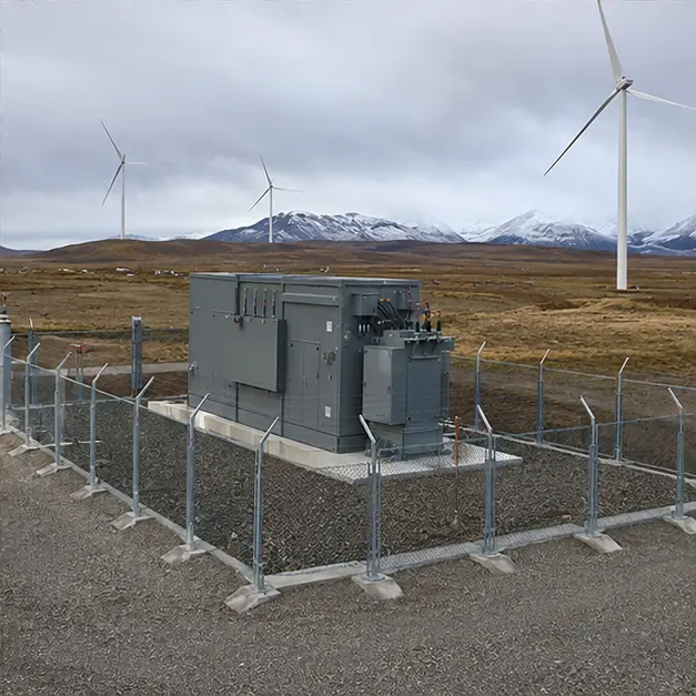
At a glance
| Country | Chile |
|---|---|
| Location | Southern Chile (as stated in the source material) |
| Application | Wind-power collection system |
| System | 33 kV prefabricated step-up substation |
| Voltage | 33 kV collector system; step-up ratio fixed against the grid connection point |
| Frequency | 50 Hz |
| Standards basis | IEC 62271-202 (prefabricated HV/LV substation), IEC 62271-200 (MV switchgear), IEC 60076 series (transformer), IEC 61439-1/-2 (LV assembly), IEC 60529 (IP), ISO 12944 (corrosion protection), NCh 432 (wind loading) and NCh 433 (seismic design), with SEC and the Chilean grid code governing the connection |
| Visual status | Representative project visualization |
The engineering problem
A wind farm in southern Chile puts three constraints on a substation before any electrical question is asked: how it gets there, what the wind does to it, and what the cold does to it.
Access first. Wind-farm roads are built for turbine blades and tower sections — wide radii, controlled gradients, engineered crossings — but they are unsealed, they are built to a budget, and they degrade in a wet southern winter. A prefabricated substation has to fit inside the same transport envelope that the turbine components defined, which means its width, height, length and mass are design inputs rather than outcomes. Splitting a substation into two shippable modules is often cheaper than upgrading a culvert.
Wind loading is the second. The same resource that justifies the site acts on the enclosure, on doors and louvres, and on any external structure, cable gantry or fence. Under NCh 432 the design wind pressure sets the enclosure’s structural framing, the anchoring detail to the foundation, and the latching of every panel that can be caught open. Wind-driven rain and, on exposed sites, wind-driven grit reach seals that would never be tested in still air, so the ingress protection has to be proved against driven water rather than vertical rain.
Cold is the third. Low ambient raises oil viscosity and slows convective cooling on start-up, stiffens gaskets and cable insulation, and makes condensation on internal surfaces the routine state rather than the exception. Anti-condensation heating, sealed and drained cable entries and the correct low-temperature rating on steel, seals and cable are the practical answers.
Electrically, the collector duty is cyclic and bidirectional, with converter-derived harmonics and long periods at light load — which makes no-load loss and thermal cycling, not steady full-load heating, the dominant design concerns.
System configuration
| Item | Description | Specification notes |
|---|---|---|
| Prefabricated enclosure | Factory-integrated outdoor substation, single unit or split modules, skid or plinth mounted | Structural framing and anchoring designed to the site design wind pressure under NCh 432 and seismic demand under NCh 433; transport envelope matched to the wind-farm access road |
| Step-up transformer | Collector-side 33 kV transformer, oil-immersed or cast-resin dry-type | Impedance and vector group set by the collector study and the turbine converter earthing requirement; harmonic loading and cyclic wind duty accounted for in loss and temperature rise calculation |
| MV switchgear | 33 kV incoming, bus-section and outgoing collector feeders | SF6, solid-insulated or air-insulated to IEC 62271-200; loss-of-service continuity and internal arc classification agreed for the enclosure layout |
| Protection and control | Overcurrent, earth-fault, directional and where required differential protection, with grid-code functions | Grid-code compliance — voltage and frequency ride-through, reactive capability, rate-of-change protection — set against the connection requirements |
| Cable interface | Collector cable entries, gland plates, screen bonding and internal routing | Sealed and drained entries; bending radius checked at low temperature, where cable is stiffest; non-magnetic gland plates for single-core cable |
| Thermal and climate control | Anti-condensation heating, controlled ventilation or air conditioning, low-temperature-rated seals | Heating sized to hold internal surfaces above dew point through the coldest night condition; ventilation openings shielded against wind-driven rain and snow |
| Earthing | Internal earth bar, enclosure and equipment bonding, connection to the site earth grid | Conductor sized for prospective earth-fault current and clearing time; step and touch potential assessed for the fenced compound |
| Auxiliary supply | LV auxiliary board, battery and charger for protection, control and heating | Battery autonomy set for a site where a call-out may take a day; heating load included in the auxiliary sizing |
| Monitoring and communication | Status, alarm, temperature and metering data to the wind farm SCADA | IEC 61850, IEC 60870-5-104 or DNP3; remote supervision is not optional on a site of this remoteness |
Installation sequence
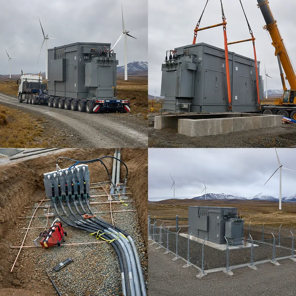
Overview
The contact sheet sets out the four stages of an installation of this type: heavy transport along the wind-farm access road, crane placement on the prepared foundation, medium-voltage cable and earthing work, and the completed fenced installation. The order is set by what becomes unreachable. Foundation, earth grid, ducts and drainage are completed and proved before the unit lands. Collector cables are pulled and left long, terminated only once the enclosure is set and its entries are positioned. Testing that needs panels open is completed before the compound is closed. Every stage is planned around a weather window, because a southern-Chile front can suspend both the lift and the road.
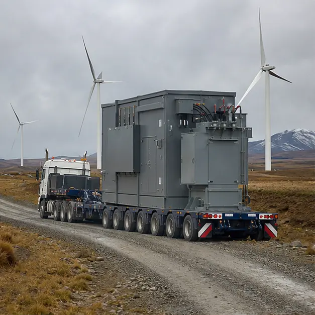
Delivery
Transport is the stage most likely to derail the programme. The route is surveyed for axle loading, gradient, camber, culvert and bridge capacity and turning radii before dispatch, and the assessment is repeated against the road’s actual condition rather than its as-built drawing — an unsealed wind-farm road after winter is not the road that was handed over. A prefabricated substation is tall relative to its base, so lashing restrains lateral movement and roll rather than merely holding the unit down. On arrival the enclosure is inspected for transport damage, door, louvre and seal alignment, water ingress and shifted internal fixings; where an oil-immersed transformer is installed, oil level, pressure gauge and gasketed joints are checked before acceptance.
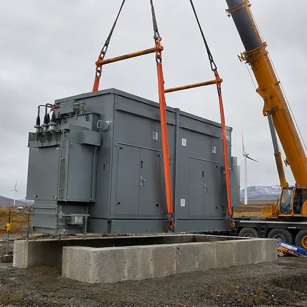
Placement
Placement is the critical lift, and on an exposed site the wind decides when it happens. Crane operations are governed by a maximum permissible wind speed at hook height, which is lower than the speed at ground level and lower again for a large-area load — a substation enclosure is essentially a sail. The lift is planned for a forecast window, with tag lines to control rotation. The foundation is confirmed level and its duct positions checked against the enclosure footprint before the unit is set down; out-of-level seating distorts door seals, defeats the ingress rating and leaves standing water on the roof. Crane capacity is assessed at working radius with outrigger bearing pressure checked on ground that may be saturated. Anchoring to the foundation is completed to the wind and seismic detail, not as a nominal fixing.
Cable work
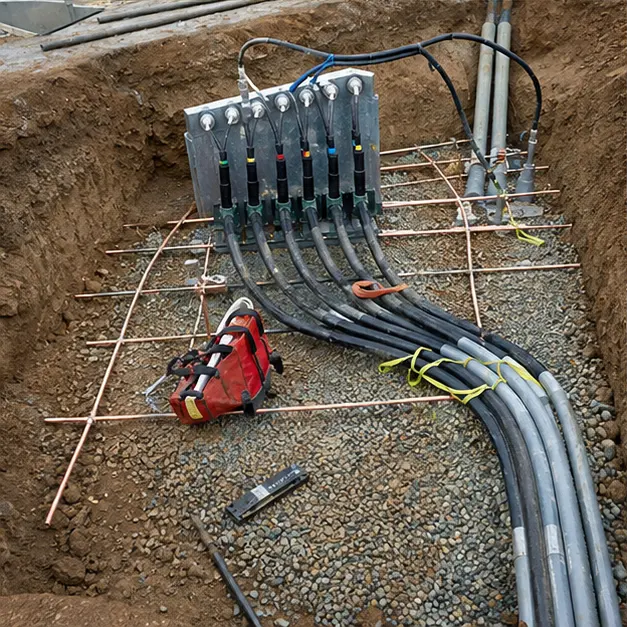
Collector cable termination is the highest-risk workmanship on the installation, and cold makes it harder. Cable is warmed and handled within its minimum bending radius, because low temperature stiffens the insulation and a radius that is acceptable in summer can crack the screen in winter. Terminations follow the usual discipline — cut-back length, semiconducting layer removal, cleanliness, correct stress-cone seating — completed in one controlled session in a temporary shelter rather than left part-made overnight. Screens are bonded to the internal earth bar with a conductor rated for the earth-fault duty, and the enclosure, transformer tank and switchgear frames are bonded to the site earth grid. Cable entries are sealed and drained. All busbar and terminal bolts are torqued to value and marked, since contact resistance is what turns a rated joint into a hot spot.
Completed configuration
Before energisation the installation is proved as a chain. Transformer ratio is measured on every tap and the vector group verified; winding and insulation resistance are recorded and, for oil-filled units, dielectric strength confirmed. Earth continuity is proved from every enclosure part, door and equipment frame back to the main bar, and the grid resistance is recorded. Protection is tested end-to-end by injection so relay, CT circuit, trip coil and breaker are proved together, and the grid-code protection functions are verified against the connection requirements. Anti-condensation heating, ventilation, auxiliary supply and battery autonomy are functionally checked. Energisation is staged — transformer charged unloaded, collector feeders energised in turn, then turbines released progressively.
Specification options
For a comparable wind enquiry, MARS can configure the voltage ratio and tapping range, transformer capacity, vector group and impedance against the collector study and the turbine converter’s earthing requirement, with copper or aluminium windings. The transformer can be oil-immersed, supplied with a less flammable ester fluid where fire separation is constrained, or cast-resin dry-type. MV switching can be SF6, solid-insulated or air-insulated with withdrawable breakers, with the loss-of-service continuity and internal arc classification to suit. Enclosures can be specified for design wind pressure and seismic demand, IP rating, ISO 12944 corrosion category and coating system, low-temperature-rated seals and steel, anti-condensation heating, ventilation or air conditioning, and split into transportable modules to suit the access road. Protection, grid-code functions, auxiliary supply autonomy and reporting over IEC 61850, IEC 60870-5-104 or DNP3 can all be configured.
What we need to quote a comparable system
Send as many of the following as you have. Missing items are not a problem — we will ask.
- Single-line diagram of the collector system and the intended step-up arrangement
- Collector voltage, transmission connection voltage, tapping range and required vector group
- Transformer capacity, wind farm installed capacity and the expected generation duty profile
- Turbine make and converter type, including harmonic content and earthing requirements
- Fault level at the point of connection, required withstand rating and clearing time
- Grid-code requirements applying at the connection point, including reactive and ride-through obligations
- Protection philosophy and any existing grading or protection coordination study
- Site design wind speed and exposure category, seismic zone, and minimum and maximum ambient temperature
- Snow, icing and wind-driven rain exposure, and the required enclosure IP and corrosion class
- Foundation arrangement, duct positions and available compound area
- Auxiliary supply requirement, battery autonomy and the SCADA protocol and points list
- Access road survey — permissible axle loading, gradients, radii, headroom — available crane capacity and delivery terms