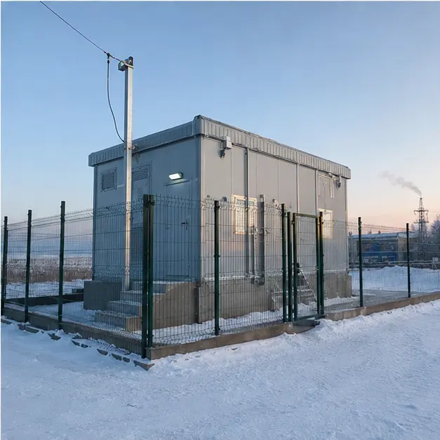
At a glance
| Country | Kazakhstan |
|---|---|
| Application | Remote industrial power supply |
| System | 35 kV/10 kV thermally insulated prefabricated substation |
| Voltage | 35 kV incoming / 10 kV outgoing |
| Frequency | 50 Hz |
| Standards basis | IEC 62271-202 (prefabricated HV/LV substation), IEC 62271-1 and -200 for the switchgear including the low-temperature class, IEC 60076 series for the transformer, IEC 61439 for LV assemblies, IEC 60529 for ingress protection; GOST 15150 climatic version for the region and the EAEU technical regulations TR CU 004/2011 and TR CU 020/2011 for market access; MARS holds an EAEU EAC declaration valid to 15 April 2029 |
| Visual status | Representative project visualization |
The engineering problem
The specification that matters in Kazakhstan is not the low temperature on its own. It is the annual swing. A remote site can sit near −40 °C in winter and near +40 °C in summer, and an 80-kelvin range is a harder brief than either endpoint taken alone, because every material in the enclosure has to stay within its working envelope at both ends and to survive the cycling between them.
Sealing is the clearest case. Elastomer gaskets stiffen as they approach their glass transition, and a compound chosen for its high-temperature rating may take a compression set in summer and then lose contact pressure in winter, at which point a sealed enclosure quietly stops being sealed. The gasket compound, the compression it is designed for, and the differential expansion between steel, aluminium and the sealing material are chosen against the full range rather than the extreme.
The same logic runs through the electrical equipment. SF6 liquefies at a temperature that depends on filling density, so switchgear for this duty is either vacuum-interrupter based, solid-insulated, or specified with a filling density and low-temperature class that keeps the gas gaseous. Mechanism lubricants, cable insulation, battery capacity, display technology and moulded-case device characteristics all shift at −40 °C.
Condensation is then the residual risk. Warm humid air admitted into a cold enclosure, or a cold enclosure warmed rapidly, deposits moisture on insulation. Anti-condensation heating, controlled ventilation and sealed cable entries exist to keep the internal dew point below the coldest surface, and they are a continuous requirement rather than a winter one.
System configuration
| Item | Description | Specification notes |
|---|---|---|
| Enclosure | Thermally insulated prefabricated substation enclosure, skid or plinth mounted | Insulation thickness and thermal bridging designed to hold internal temperature with the specified heater load; roof profile and structure rated for snow and wind loading; IP rating maintained across the temperature range |
| Sealing system | Door, panel, louvre and gland-plate gaskets | Compound selected for low-temperature flexibility and compression set resistance over the full annual range; compression set by the design rather than by the fixings, and differential expansion between steel and aluminium accounted for |
| MV switchgear | 35 kV incoming and 10 kV outgoing switching and protection | Vacuum or solid-insulated switching preferred for low-temperature service; where SF6 is used, filling density and the minimum ambient class are declared; mechanism lubricants rated for the minimum temperature |
| Transformer | 35 kV/10 kV transformer | Oil-immersed with a low pour-point oil and a defined cold-start procedure, or cast-resin dry-type where cold-start behaviour and containment govern; tapping range set against the network's voltage variation |
| Space and anti-condensation heating | Enclosure space heating plus panel and mechanism heaters | Heater load sized on the enclosure heat loss at the minimum design ambient; anti-condensation heaters controlled from humidity and temperature rather than left permanently on; separate supply so that heating survives an outage of the main circuit |
| Ventilation | Controlled, thermostatically staged ventilation with snow-proof louvres | Ventilation removes summer loss heat and must not admit drifting snow or humid air in winter; louvre and filter arrangement designed against both |
| Cable entries | Sealed MV and LV entries through gland plates | Entries sealed against moisture, drifting snow and vermin; non-magnetic gland plates for single-core cables; entry position kept above the drift line |
| Foundation and anchoring | Raised foundation designed for the local frost depth | Founded below the frost line or on a design that tolerates frost heave; raised plinth keeps entries and floor clear of snow accumulation, and anchoring is designed against wind loading on a tall enclosure |
| Auxiliary supply and monitoring | Auxiliary transformer, DC supply, heating control, temperature, humidity, door and alarm monitoring | Battery type and location chosen for cold-temperature capacity; remote monitoring reported over Modbus RTU/TCP, IEC 61850 or IEC 60870-5-104 where a site of this type is unmanned |
Installation sequence
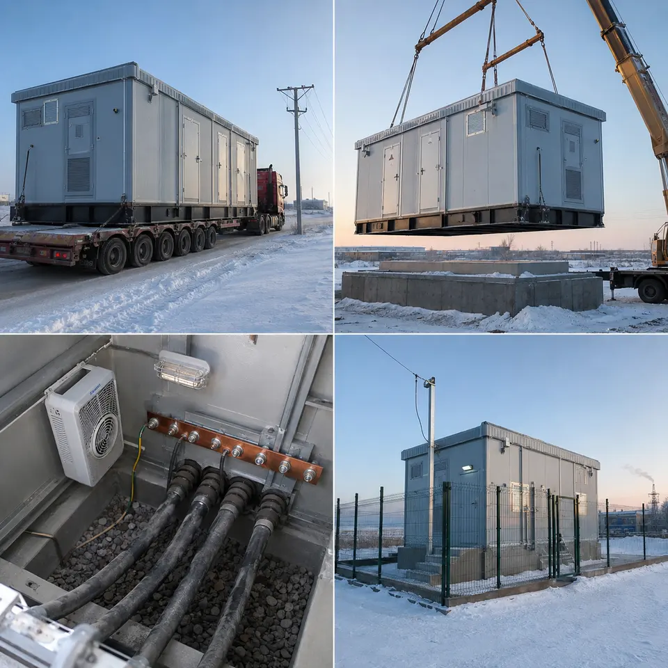
Overview
The contact sheet sets out the four stages of an installation of this type: winter transport, crane placement on the raised foundation, cable-entry and anti-condensation work, and the completed fenced installation. Cold weather compresses the working window at every stage, so the order is set by what cannot be done later. Foundation, ducts and earth electrode are complete and proved before frost closes the ground. Placement is planned for a period when the crane can be set up and the enclosure landed without ice on the lifting points. Cable and sealing work is done inside a heated enclosure, and heating is commissioned before, not after, the internal work that depends on it.
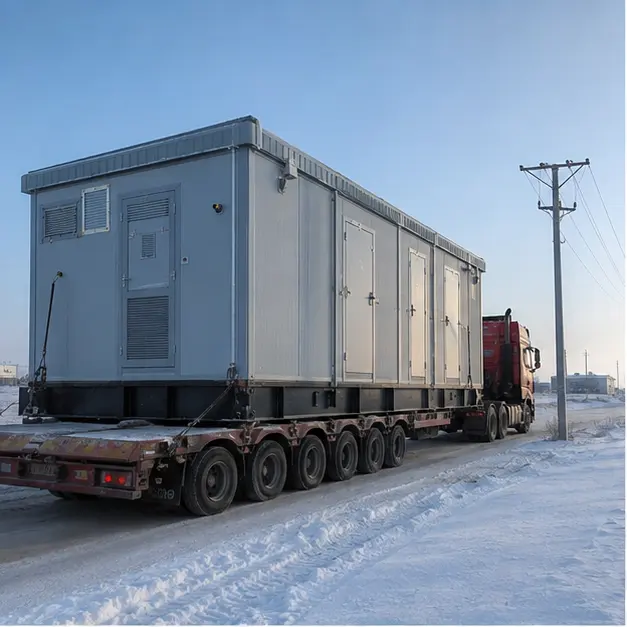
Delivery
Winter road transport is a load-securing problem before it is a scheduling one. Lashings lose tension as steel contracts, so tension is checked at intervals rather than set once at the works. Braking distances on ice govern route timing, and a tall enclosure with a high centre of gravity is exposed to crosswind on open steppe. Equipment travels with its own protection: transformer oil at a temperature the pour point permits, desiccant breathers sealed, and battery and electronic items either removed or transported in a heated space. On arrival the unit is inspected before acceptance for transport damage, seal condition, ice and snow ingress, and shifted internal fixings. Equipment is allowed to equalise before enclosures are opened, since opening a cold panel into warmer air condenses moisture directly onto insulation.
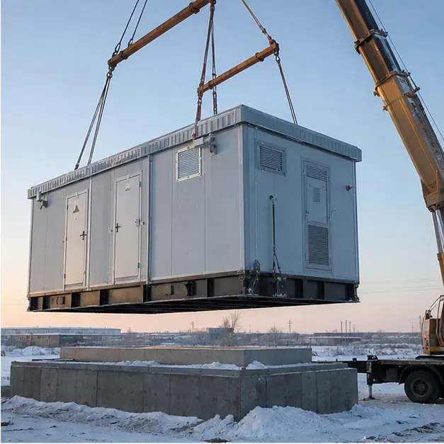
Placement
Placement onto the raised foundation is the critical lift and the one most constrained by weather. Crane capacity is derated for wind, and lifting is suspended above the wind limit rather than judged on site. Outrigger bearing pressure is assessed on ground that may be frozen crust over soft material, which can be strong in the morning and not by afternoon. The lift uses the designated corner or lug points with a spreader beam so slings do not bear on the insulated wall panels, which are more easily damaged than a bare steel enclosure. The foundation is confirmed level before the unit is set down, because an out-of-level enclosure distorts door seals and compromises the sealing on which the whole thermal design depends. Anchoring is completed to the wind and frost-heave detail rather than left nominal.
Internal work
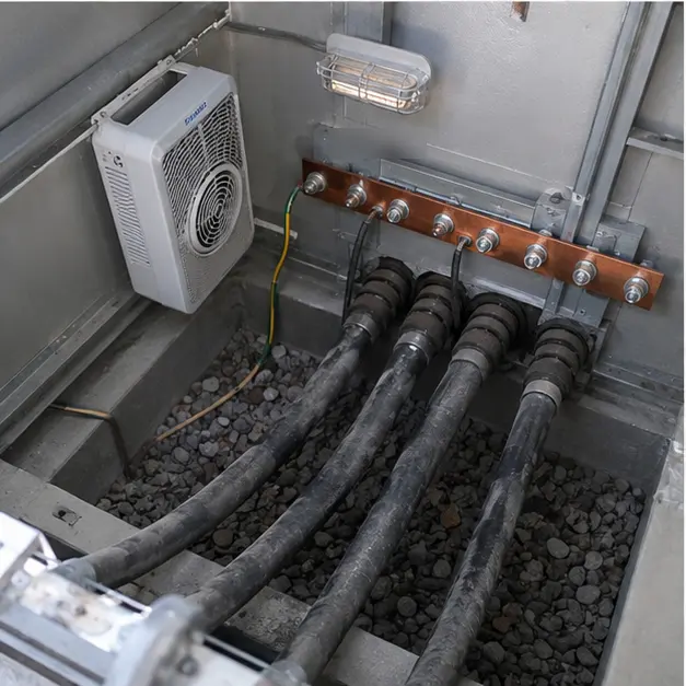
This stage decides whether the enclosure stays dry for the rest of its life. MV cable is warmed before pulling, because XLPE stiffens in the cold and a cable bent below its minimum radius when cold can be damaged in a way that only shows up as a termination failure later. Terminations are made in a heated, dry space and completed in one working period rather than left part-finished overnight. Gland plates and entry seals are fitted so that the enclosure’s ingress rating is continuous through the entry, and the entry is checked for a path that would let drifting snow reach the inside. Cable screens are bonded to the internal earth bar with a conductor sized for the earth-fault duty. Space and anti-condensation heaters, their thermostats and humidistats and their separate supply are then wired and functionally proved, and the ventilation staging is set so that it cannot draw humid air in during a winter warm spell.
Completed configuration
The completed configuration shows the substation fenced, sealed, insulated and labelled on its raised foundation. Before energisation the installation is proved as a chain: transformer ratio and vector group on every tap, insulation resistance recorded with the ambient temperature noted because the reading is temperature dependent, earth continuity confirmed from every enclosure part back to the main bar, and the earth electrode resistance measured and recorded with the ground condition stated, since frozen ground reads differently from thawed. Protection is proved end-to-end by injection. Heating, ventilation, humidity control and any remote monitoring are functionally checked, including behaviour on loss of the auxiliary supply. Energisation is staged, with an oil-filled transformer given the cold-start soak its procedure requires before load is applied.
Specification options
For a comparable cold-climate enquiry, MARS can adapt the voltage ratio and tapping range, capacity, vector group and impedance, with oil-immersed or cast-resin dry-type transformers and a cold-start procedure defined for the minimum ambient. Enclosures can be supplied with a stated thermal insulation performance, IP rating, corrosion category and coating class, with roof and structure rated for the site’s snow and wind loading. Switching can be vacuum, solid-insulated or SF6 with a declared minimum ambient class and filling density. Heating can be specified as enclosure space heating plus panel and mechanism anti-condensation heaters with humidity and temperature control on a separate supply, and ventilation as thermostatically staged with snow-proof louvres. Sealed cable entries, low-temperature battery arrangements, cold-rated lubricants and displays, and remote monitoring over Modbus, IEC 61850 or IEC 60870-5-104 can all be configured, together with EAEU conformity documentation for the region.
What we need to quote a comparable system
Send as many of the following as you have. Missing items are not a problem — we will ask.
- Single-line diagram of the incoming supply and the intended 10 kV distribution arrangement
- Incoming 35 kV details, tapping range and step size, and the required vector group
- Transformer capacity, site load profile and any motor starting or drive-fed load
- System fault level at the point of connection, required withstand rating and clearing time
- Protection philosophy, relay preferences and any utility-imposed settings or grading requirement
- Minimum and maximum design ambient temperature, and the site's design snow and wind loading
- Altitude, humidity range and the applicable GOST 15150 climatic version
- Frost depth and ground conditions, and whether the foundation is raised or at grade
- Auxiliary supply arrangement, required heating strategy and the acceptable heater energy consumption
- Enclosure IP rating, thermal insulation requirement, corrosion category and coating specification
- Communication protocol, remote monitoring points list and whether the site is unmanned
- Conformity documentation required for import, site access route in winter conditions, permissible axle loading, crane availability and delivery terms