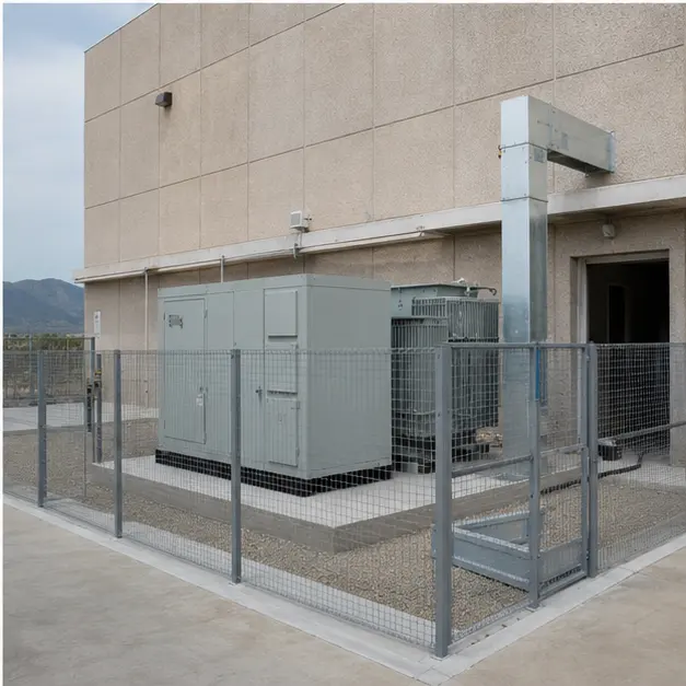
At a glance
| Country | Mexico |
|---|---|
| Location | Monterrey (as stated in the source material) |
| Application | Automotive components manufacturing plant |
| System | 13.8 kV/480 V compact substation with coordinated MV and LV switchgear and bus duct |
| Voltage | 13.8 kV incoming / 480 V outgoing |
| Frequency | 60 Hz |
| Standards basis | NOM-001-SEDE (Instalaciones Eléctricas) in the edition current at the time of supply, with NMX-J standards administered through ANCE and CFE's own equipment specifications for anything interfacing with the utility network; ANSI/IEEE C57 series for the transformer, IEEE C37 series for the switchgear, IEEE 519 for harmonic limits at the point of common coupling, IEEE 242 practice for protective device coordination, NFPA 70E and IEEE 1584 practice for arc-flash assessment |
| Visual status | Representative project visualization |
The engineering problem
Mexico is an ANSI market on a 60 Hz system, and both halves of that sentence change the equipment. The 480 V secondary is a North American industrial voltage, so the LV switchgear, motor control and bus duct follow ANSI/IEEE and NEMA practice rather than the IEC 400 V conventions used elsewhere. At 60 Hz the core operates at a different volts-per-turn for the same flux density, so a transformer designed for a 50 Hz market is not interchangeable — core cross-section, losses, sound level and the ratings of magnetics throughout the installation all differ. Specifying an IEC 50 Hz unit against a Mexican single-line is one of the more expensive mistakes available on a project of this kind. Where the equipment interfaces with the utility, CFE’s own specifications apply on top of the national installation standard, and compliance is evidenced through certification to the applicable NMX standards.
The plant load is the second driver. An automotive components factory presents two awkward load types at once. Variable-speed drives on presses, conveyors and machine tools inject characteristic harmonic currents that raise transformer winding eddy losses and can excite resonance with power-factor correction capacitors. Resistance welding is worse in a different way: short, heavy, often single-phase draws that produce voltage flicker and phase unbalance rather than steady distortion. IEEE 519 sets what can be pushed back to the point of common coupling, but the internal problem — holding voltage steady enough for the welders and the drives to work reliably — is decided by transformer impedance, bus duct rating and where the correction and filtering sit.
Protection coordination ties the two together. Grading from the utility interface through the transformer to the 480 V main and the outgoing feeders has to clear a fault fast enough to keep arc-flash energy manageable while still holding selectivity, so that a fault on one production line does not take the plant down.
System configuration
| Item | Description | Specification notes |
|---|---|---|
| Compact substation | Outdoor compact or box-type substation housing MV switching, transformer and LV interface | Enclosure IP rating, corrosion category and coating specified for the local climate; foundation, clearances and access arranged for utility and plant maintenance separately |
| MV switchgear | 13.8 kV incoming switching, protection and metering | Metal-enclosed or metal-clad arrangement to IEEE C37 practice; interrupting rating set by the utility fault level; utility metering compartment and sealing arranged to CFE requirements |
| Transformer | 13.8 kV/480 V, 60 Hz, delta primary and earthed star secondary | ANSI/IEEE C57 basis; core and coil designed for 60 Hz; impedance chosen low enough to hold voltage under welding and motor starting yet high enough to keep 480 V fault current within the switchgear rating; K-factor or harmonic loss allowance set against the drive content |
| LV switchgear and bus duct | 480 V main switchboard, feeder sections and bus duct to the plant electrical room | Bus duct continuously rated for the full transformer output with the correct temperature rise and short-circuit bracing; expansion fittings on long runs; ampacity checked at the actual ambient inside the plant |
| System earthing | Solidly earthed or high-resistance earthed 480 V neutral | High-resistance earthing keeps the plant running through a first earth fault, which suits continuous production, but requires a fault-locating scheme and insulated-neutral discipline; the choice is made against the plant's tolerance for unplanned stoppage |
| Protection and coordination | MV overcurrent and earth fault, transformer protection, LV main and feeder devices | Time-current grading verified by a coordination study; arc-flash incident energy assessed and labelled; instantaneous and maintenance settings arranged so that work on live equipment is not the default |
| Power quality | Power-factor correction, detuned reactors or harmonic filtering as required | Correction detuned or filtered where drive content risks resonance; flicker from welding assessed separately from harmonic distortion, since the mitigation is not the same |
| Metering and monitoring | Utility metering, plant sub-metering, power quality recording | Permanent recording at the main incomer gives the record needed to resolve a power-quality dispute or a production complaint |
| Communication | Gateway to the plant energy management or SCADA system | Modbus RTU/TCP, DNP3 or IEC 61850 depending on the plant's existing system and points list |
Installation sequence
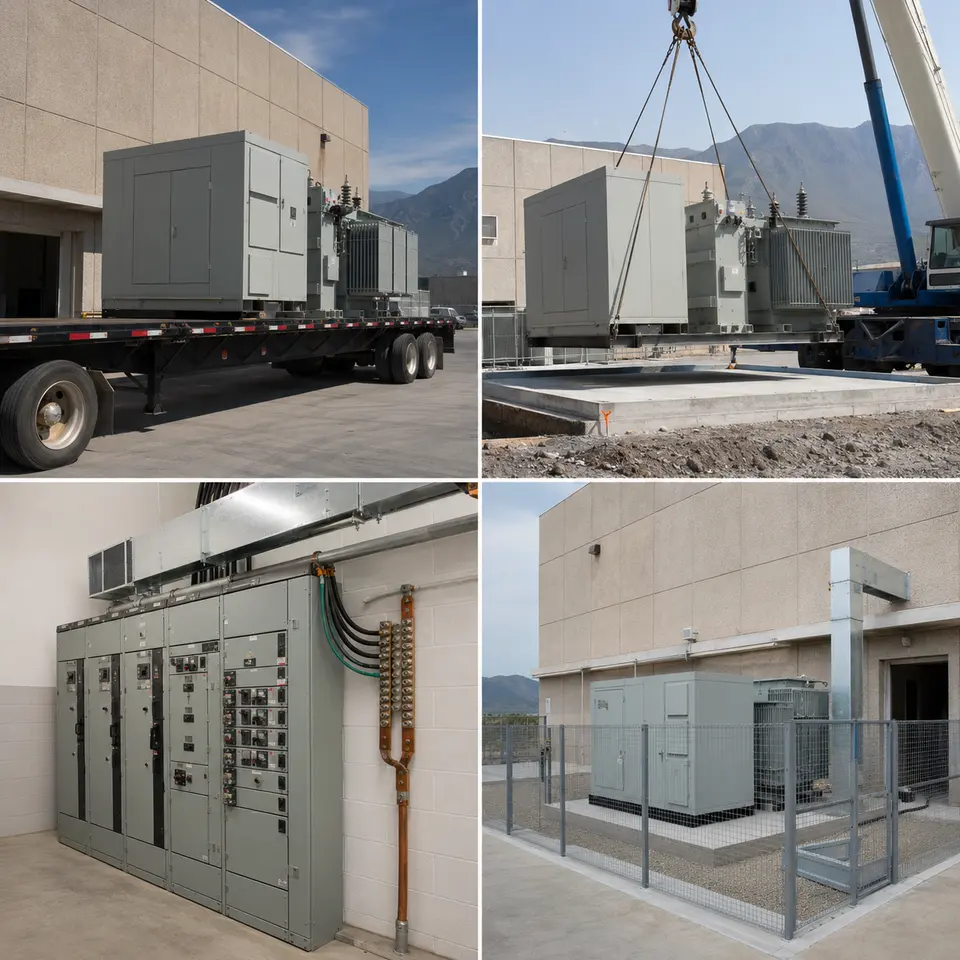
Overview
The contact sheet sets out the four stages of an installation of this type: equipment delivery, crane positioning on the outdoor foundation, indoor switchgear and bus duct connection, and the completed fenced installation beside the plant electrical room. The order is set by what becomes inaccessible and by what the factory can tolerate. Foundation, ducts, earth grid and drainage are completed and proved before the substation lands. Bus duct is measured on the built geometry between the outdoor unit and the indoor board rather than cut from a drawing. Testing that requires panels open is completed before the compound is closed, and the connection to production loads is staged around a shutdown window that the plant will not want to extend.
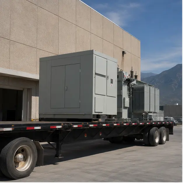
Delivery
Delivery is planned against the plant site rather than against open road. Route survey covers axle loading, gradients, gate and yard turning radii, overhead services and the crane standing position, which on a working factory site is often the real constraint. The unit is lashed to restrain lateral movement, since a compact substation is tall relative to its base and its mass is concentrated low and off-centre where the transformer sits. On arrival it is inspected before acceptance: enclosure for transport damage, door and louvre alignment and seal condition, internal equipment for shifted fixings, transformer for oil level and gasketed joints or, for a cast-resin unit, for cracking or chipping at coil ends. Insulation resistance is measured on receipt as a baseline.
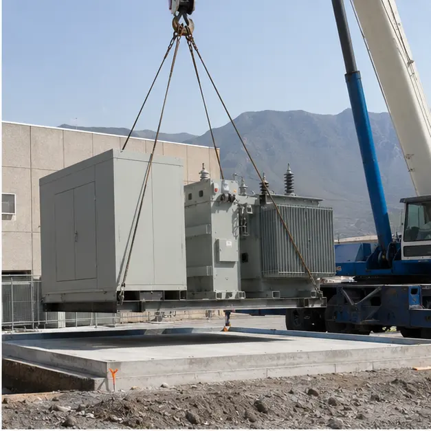
Placement
Placement onto the outdoor foundation is the critical lift. Lifting uses the designated lugs or corner points with a spreader beam so slings do not bear on the enclosure walls, and crane capacity is assessed at working radius with outrigger bearing pressure checked against the yard surface, which in a factory yard often conceals ducts and drainage. The foundation is confirmed level before the unit is set down: an out-of-level enclosure distorts door seals, compromises the ingress rating and misaligns the bus duct flange that the indoor run has to meet. Clearances to the building, to the boundary and to vehicle routes are confirmed against the layout and against the access the utility will require to its metering compartment. Anchoring is then completed to the wind and seismic detail for the location rather than left as a nominal fixing.
Internal work
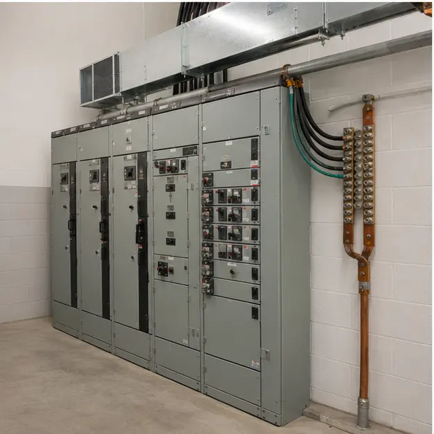
Indoor work covers the 480 V switchboard, the bus duct run and the earthing system. Bus duct is set out with its expansion fittings positioned to absorb thermal movement, supported at the specified intervals, and aligned so that joints are not pulled into position — a strained joint is a hot joint. Joint bolts are tightened to the specified torque with the manufacturer’s indicating method and each joint marked, because contact resistance is what turns a rated connection into a failure. Phase sequence and phase identification are verified through the run before it is closed. The switchboard is bonded to the plant earth grid with a conductor sized for the prospective earth-fault current and clearing time, and the bus duct enclosure is bonded continuously through every joint. Insulation resistance is measured on the completed run, and interlocks are proved by operation rather than by inspection.
Completed configuration
The completed configuration shows the compact substation fenced and labelled outside the plant, feeding the indoor 480 V board through bus duct. Before energisation the installation is proved as a chain: transformer ratio and vector group on every tap, winding resistance and insulation resistance recorded, earth continuity confirmed from every enclosure back to the grid, and protection proved end-to-end by injection so relay, CT circuit and trip device are shown to work together. Coordination and arc-flash study results are checked against the settings actually applied, and labels are fitted to match. Energisation is staged — transformer charged unloaded, then the 480 V board, then production loads applied line by line — with voltage, unbalance and distortion recorded during the first welding and drive operation, since those are the conditions the impedance and the power-quality design were chosen against.
Specification options
For a comparable factory enquiry, MARS can engineer the voltage ratio and tapping range, capacity, vector group and impedance against the plant’s motor and welding duty, at 60 Hz, with copper or aluminium windings. The transformer can be cast-resin dry-type for indoor placement or oil-immersed with containment for outdoor, with insulation class, temperature-rise limits and a harmonic loss allowance set against the drive content. MV switching can be metal-enclosed or metal-clad with the required interrupting rating and a utility metering compartment. LV switchboards can be supplied to the required short-circuit rating, bracing and access arrangement, with bus duct rated and braced for the transformer output. Enclosures can be specified for IP rating, corrosion category and coating class. Power-factor correction can be plain, detuned or filtered, and monitoring can extend to permanent power quality recording reported over Modbus, DNP3 or IEC 61850.
What we need to quote a comparable system
Send as many of the following as you have. Missing items are not a problem — we will ask.
- Single-line diagram of the utility interface, the substation and the 480 V distribution
- Incoming 13.8 kV details, tapping range and step size, and the required vector group
- Transformer capacity, plant load profile, load factor and any planned production expansion
- Motor schedule with the largest motor and its starting method, and the variable-speed drive inventory with expected harmonic spectrum
- Welding load description — type, duty cycle, single- or three-phase — for flicker and unbalance assessment
- Utility short-circuit level at the point of common coupling and the applicable CFE specification and metering requirements
- 480 V system earthing decision — solidly earthed or high-resistance — and the plant's tolerance for a first-fault stoppage
- Protection philosophy, existing coordination study, and arc-flash assessment and labelling requirements
- Power-factor target, any existing correction equipment, and measured power quality data if available
- Room layout, bus duct route with lengths and offsets, headroom, and the indoor ambient temperature for ampacity
- Site ambient temperature range, altitude, dust exposure, corrosion category and wind and seismic design data
- Communication protocol, energy management system points list, available shutdown window and delivery terms