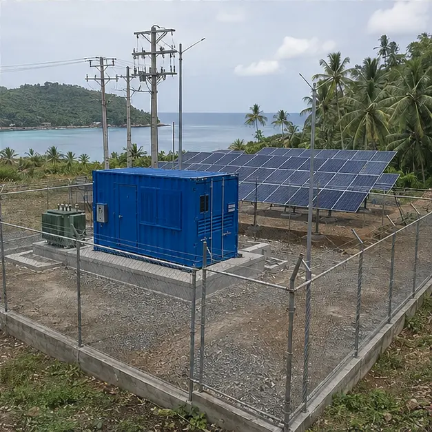
At a glance
| Country | Philippines |
|---|---|
| Application | Coastal island microgrid with solar generation and local distribution |
| System | 13.8 kV containerized substation with compact transformer and switchgear |
| Voltage | 13.8 kV distribution / low-voltage outgoing |
| Frequency | 60 Hz |
| Standards basis | Philippine Electrical Code (ANSI/IEEE practice), IEEE C57.12.00 and C57.12.90 (transformers), ANSI/IEEE C37.20.2/20.3 and C37 series (switchgear and circuit breakers), IEEE 80 (substation grounding), IEEE 1547 (distributed resource interconnection), IEEE 2030.7 (microgrid controller), NSCP wind loading, ISO 9223/ISO 12944 corrosion classification |
| Visual status | Representative project visualization |
The engineering problem
The Philippines uses ANSI/IEEE practice through the Philippine Electrical Code, so 13.8 kV is a 15 kV class system at 60 Hz — not an IEC 15 kV system with different insulation levels, clearances and equipment ratings. Getting that right at the enquiry stage avoids specifying a transformer and switchgear that are electrically correct but dimensionally and dielectrically wrong for the network they must connect to.
The defining constraint, though, is that an island microgrid has no backup feed. On a mainland network a fault means an outage until the alternative supply is switched in. Here there is no alternative supply, so redundancy has to exist inside the substation: a sectionalised bus, spare feeder capacity, a duplicated auxiliary supply, and a stock of the parts that cannot be flown in quickly. Reliability is designed in at the point of purchase because it cannot be bought later.
Low fault current is the second consequence, and it is a protection problem. A microgrid supplied largely by inverters has a fault contribution limited to roughly rated current, and it changes depending on which sources are running. Conventional overcurrent grading, which relies on a large and stable difference between load and fault current, becomes unreliable. Directional, differential or communication-assisted protection, adaptive settings, or a controller that switches setting groups by operating mode are the practical answers. Frequency control is the parallel issue: with little rotating inertia, a grid-forming source and fast frequency response are needed to survive load steps.
Environment closes the case for a containerized format. Typhoon wind loading under the NSCP, storm surge and flooding, and a marine atmosphere at the highest corrosivity category mean a sealed, anchored, elevated steel enclosure with everything of value inside it.
System configuration
| Item | Description | Specification notes |
|---|---|---|
| Container enclosure | Factory-integrated outdoor substation on a raised, flood-resilient foundation | Structural framing and anchoring designed for the NSCP basic wind speed at the site; coating system and hardware specified for a marine corrosivity category; sealed against wind-driven rain |
| Transformer | 13.8 kV compact distribution transformer, oil-immersed or cast-resin dry-type | IEEE C57.12.00 basis, 15 kV class insulation level; impedance chosen against motor starting, inverter fault contribution and LV withstand |
| MV switchgear | 13.8 kV incoming, bus-section and outgoing feeders serving the island distribution lines | Metal-enclosed or metal-clad to ANSI/IEEE C37.20; sectionalised bus so a fault or maintenance outage does not take the whole island down |
| Protection | Directional, differential or communication-assisted feeder protection with multiple setting groups | Settings grouped by operating mode, since fault current depends on which sources are running; sensitive earth-fault detection for an overhead distribution network |
| Microgrid controller | Dispatch and mode control across solar, storage, any generating set, and the local load | IEEE 2030.7 functions — mode transition, black start, load shedding, frequency and voltage regulation with a grid-forming source |
| LV distribution | LV main assembly and outgoing distribution to local feeders and station services | Form of separation and withstand rating set by the transformer rating and maintenance policy |
| Surge protection | MV and LV surge arresters at the transition to overhead distribution | Rating and energy class selected against the high lightning density and the overhead line exposure |
| Grounding | Station ground grid, enclosure and equipment bonding, cable screen and arrester earths | Designed to IEEE 80 with step and touch potential evaluated for a publicly accessible coastal site; conductor material chosen against soil chloride content |
| Thermal control and auxiliaries | Filtered ventilation or air conditioning, anti-condensation heating, station battery and charger | Cooling sized on total losses at the design ambient; battery autonomy set for an island where a technician visit may take days |
Installation sequence
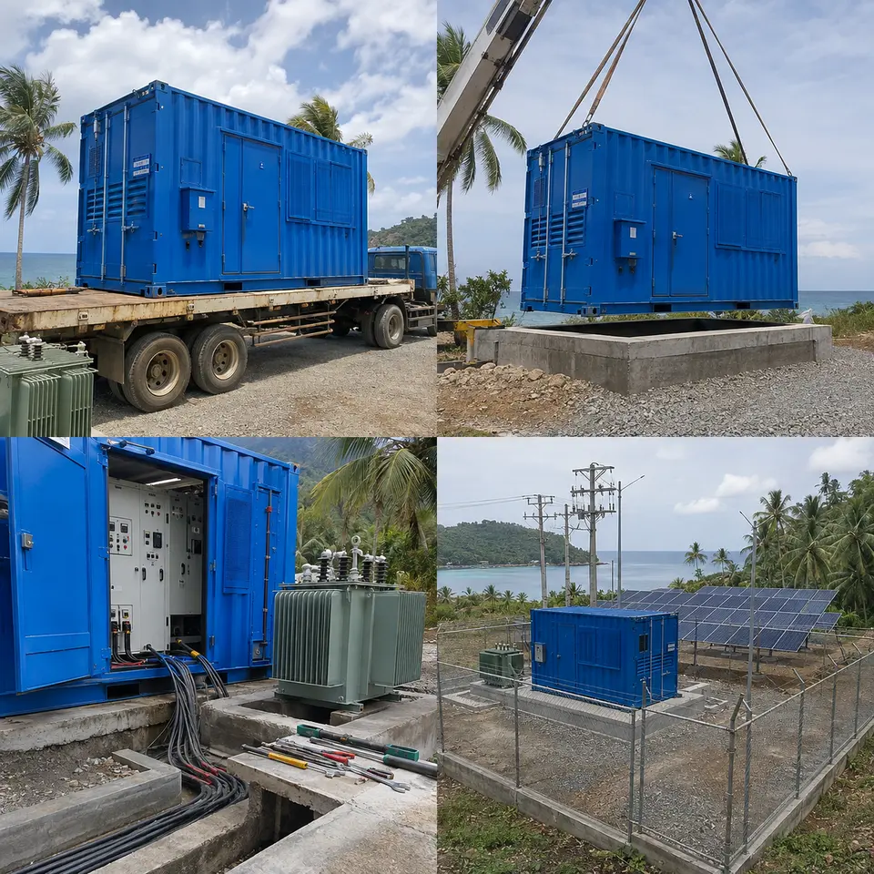
Overview
The contact sheet sets out the four stages of an installation of this type: equipment delivery to the island, crane placement onto the raised pad, switchgear and cable connection work, and the completed fenced microgrid site. The order is dictated by logistics as much as by engineering. On an island, everything that arrives has arrived deliberately, so the foundation, ground grid, ducts and drainage are complete and proved before the container lands and there is no scope for a second delivery of a forgotten item. Cable is measured on actual positions after placement. Testing that needs panels open is finished before the compound is closed, because reopening it means another boat.
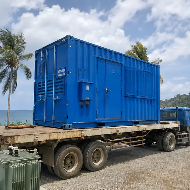
Delivery
Delivery to an island community adds a marine leg and often a beach or small-port landing to the usual road transport assessment. Barge capacity, tidal window, ramp gradient and the bearing capacity of the landing all have to be established before dispatch, and the equipment has to be protected against salt spray for the whole crossing — a container that arrives with chloride deposits on unprotected steel has already started corroding. Receiving inspection covers transport damage, seal and louvre alignment, water ingress, shifted internal fixings and, for an oil-immersed transformer, oil level and pressure gauge reading. Spares and consumables are checked against the packing list with particular care, since a shortfall cannot be made good locally.
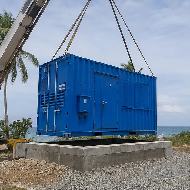
Placement
The raised pad is the defining structural feature of a coastal Philippine installation, and its height is a design decision derived from the site’s flood and storm-surge assessment, not a construction preference. It keeps the enclosure floor and cable entries above expected inundation and gives the cable trench a fall for drainage in heavy rainfall. Placement uses the designated lifting points with a spreader beam; crane capacity is assessed at working radius on ground whose bearing pressure has been checked, and the lift is scheduled inside a wind window because a container enclosure presents a large sail area. The pad is confirmed level before the unit is set down, and anchoring is completed to the full typhoon uplift and overturning detail.
Internal work
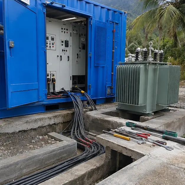
Internal work covers MV and LV cable termination, busbar connection and the grounding system. MV terminations are the highest-risk workmanship on the installation: cut-back length, semiconducting layer removal, cleanliness and correct stress-cone seating decide their life, and in tropical humidity each termination is completed in one controlled session rather than left part-made overnight. Cable screens and arrester earths are bonded to the station ground bar with conductors sized for the prospective fault current and clearing time. Bushings, insulators and any external terminations get particular attention on a salt-air site, where leakage-current tracking across contaminated surfaces is a real failure mode. Busbar and terminal bolts are torqued to value and marked.
Completed configuration
Before energisation the installation is proved as a chain. Transformer turns ratio is measured on every tap and the vector group verified; insulation resistance is recorded; ground continuity is confirmed from every enclosure part and equipment frame back to the main bar, with grid resistance and step and touch potential measured against the IEEE 80 design. Protection is tested end-to-end by injection, and each setting group is verified against the operating mode it belongs to. The microgrid controller is proved through its transitions — grid-forming start, load pickup, source changeover, load shedding and black start — because those sequences, not steady-state operation, are where a microgrid actually fails. Energisation is staged, with load applied progressively.
Specification options
For a comparable island or microgrid enquiry, MARS can configure the voltage ratio and tapping range, transformer capacity, vector group and impedance against the load profile and the inverter fault contribution, with copper or aluminium windings and 15 kV class insulation levels to ANSI/IEEE practice. The transformer can be cast-resin dry-type where fire load inside the enclosure governs, or oil-immersed with containment. MV switching can be metal-enclosed load-break or metal-clad with vacuum breakers, with sectionalising and spare feeder ways to suit the reliability target. Protection can extend to directional, differential and communication-assisted schemes with multiple setting groups. Enclosures can be specified for NSCP wind loading, raised-pad height, marine corrosion category and coating system, filtered ventilation or air conditioning, and anti-condensation heating. Storage, PCS and controller functions can be integrated, with reporting over Modbus, DNP3 or IEC 61850.
What we need to quote a comparable system
Send as many of the following as you have. Missing items are not a problem — we will ask.
- Single-line diagram of the microgrid, showing sources, the distribution network and the intended substation position
- Incoming and outgoing voltage, tapping range and required vector group
- Transformer capacity, island load profile, daily and seasonal variation, and the largest motor load
- Generation mix — solar capacity, storage energy and power, any generating set — and which source is grid-forming
- Expected fault current from each source and in each operating mode, and the required protection philosophy
- Reliability target, required redundancy, and the sectionalising and spare feeder arrangement
- Site ambient temperature range, humidity, NSCP basic wind speed, flood and storm-surge levels
- Marine corrosivity classification, required enclosure IP rating, coating system and hardware material
- Soil resistivity and chemistry for the ground grid design, and the available compound area
- Station battery autonomy required and the auxiliary supply arrangement
- Microgrid controller functions required, communication protocol and any remote supervision
- Delivery route including the marine leg, landing constraints, available crane capacity and delivery terms