Key takeaways
- A 12 volt landscape lighting transformer steps 120 V or 230 V mains supply down to extra-low voltage (12 V to 15 V AC) to meet safety standards including UL 1838 and NEC Article 411.
- A multi tap landscape lighting transformer provides boosted output terminals (12 V, 13 V, 14 V, and 15 V) to compensate for voltage drop across long outdoor secondary cable runs.
- Transformers supplying outdoor architectural luminaires must be continuously loaded to no more than 80% of their rated capacity to ensure long service life and accommodate LED driver inrush current.
- Toroidal core transformers deliver electrical efficiencies exceeding 94% with lower audible hum and reduced excitation losses compared to traditional stacked EI-laminated magnetic cores.
- Implementing balanced star or centre-fed hub cabling layouts prevents uneven terminal voltages across multi-fixture luminaire runs.
Quick answer: A 12 volt landscape lighting transformer is a specialised step-down isolating transformer that reduces 120 V or 230 V nominal mains supply to a safe secondary operating range of 12 V to 15 V AC. It incorporates thermal, magnetic, and ground-fault protection to supply exterior architectural and pathway luminaires under continuous outdoor duty cycles.
In municipal, commercial, and expansive residential perimeter lighting networks, power distribution requires strict electrical safety alongside photometric consistency. Long secondary cable runs inevitably suffer from voltage drop, which produces uneven illumination or causes modern LED drivers to drop out prematurely. Understanding how to select the right magnetic core construction, size total volt-ampere loads, and configure a multi tap low voltage transformer ensures that installations remain compliant with regional electrical codes while delivering rated luminous flux across every connected fixture. For broader principles on step-down systems, see our single phase transformer guide.
What Is a 12 Volt Landscape Lighting Transformer?
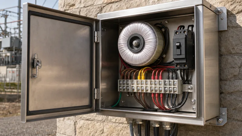
A 12 volt landscape lighting transformer is a dedicated step-down dry-type power unit designed to supply low-voltage outdoor lighting circuits from standard distribution voltages. Governed by standards such as UL 1838 and NEC Article 411 in North America, and IEC 61558-2-6 internationally, these units isolate secondary distribution from the high-voltage mains via an electrostatic shield between primary and secondary copper windings.
Unlike indoor utility transformers, outdoor lighting units are housed in weatherproof enclosures—typically 304 or 316 stainless steel with an ingress protection rating of IP65 or NEMA 3R. Commercial-grade units incorporate dual primary thermal protection, primary circuit breakers, and secondary magnetic circuit breakers for each discrete output run. The core provides galvanic isolation, eliminating lethal shock hazards near damp soil, water features, and public footpaths. Sizing strategies share fundamental similarities with those detailed in our low voltage landscape lighting transformer sizing guide.
How a Multi Tap Landscape Lighting Transformer Compensates for Voltage Drop
A multi tap landscape lighting transformer solves the problem of secondary conductor line resistance by providing multiple discrete output terminals rated from 12 V up to 15 V. Because alternating current flowing through long low-voltage conductors experiences voltage drop proportional to circuit impedance and loop length, terminal voltages at the end of a line can drop well below the 10.5 V minimum threshold required by standard LED drivers.
A typical commercial multi tap low voltage transformer provides output taps arranged in stepped increments: 12 V, 13 V, 14 V, and 15 V (and occasionally 11 V for high-line utility conditions). By connecting distant runs to the 14 V or 15 V terminal, field technicians ensure that voltage arrives at the first fixture below the maximum safe continuous threshold (typically 12.5 V AC) while maintaining at least 11.0 V AC at the final luminaire. Field testing must verify that no fixture receives more than 15 V at zero load, adhering strictly to UL 1838 Clause 19 safety cut-offs.
Sizing Calculations: Load, Power Factor, and Inrush Capacity
Sizing a 12 volt landscape lighting transformer requires calculating the total volt-ampere (VA) demand rather than relying purely on nominal LED wattage ratings. LED luminaires use electronic internal drivers that exhibit non-linear current characteristics, creating a power factor (PF) typically ranging between 0.65 and 0.85, alongside instantaneous inrush currents during switch-on cycles.
To calculate the correct transformer capacity, apply the following standard engineering steps:
- Sum the actual wattage of all connected lamps and luminaires on the circuit.
- Divide the total wattage by the luminaire power factor (use 0.70 if unverified) to establish the true apparent power demand in volt-amperes (VA).
- Apply the continuous-load de-rating factor defined in NEC Article 215 by multiplying the total VA by 1.25 (limiting maximum continuous operation to 80% of transformer nominal capacity).
- Select the next standard commercial transformer rating (e.g., 150 VA, 300 VA, 600 VA, 900 VA, or 1200 VA).
Consider a practical engineering calculation for an exterior perimeter run. A project specifies 28 LED pathway and wall-wash luminaires rated at 6 W each, operating over 65 metres of conductor:
$$\text{Active Power } P = 28 \times 6\text{ W} = 168\text{ W}$$
$$\text{Apparent Power } S = \frac{168\text{ W}}{0.75\text{ PF}} = 224\text{ VA}$$
$$\text{Required Transformer Sizing} = 224\text{ VA} \times 1.25 = 280\text{ VA}$$
A 300 VA multi-tap unit is the minimum acceptable capacity. Sizing at or below 224 VA causes primary winding overheating and nuisance tripping of secondary thermal-magnetic breakers during cold-start inrush. For further details on matching low-voltage units to solid-state drivers, refer to our guide on low voltage transformers for LED lights.
Toroidal vs EI Laminated Magnetic Cores
The choice between toroidal and stacked EI laminated core topologies dictates overall transformer efficiency, operating temperature, physical dimensions, and acoustic noise. Both core types appear in commercial low-voltage lighting gear, but their performance profiles suit distinct project constraints.
| Engineering Metric | Toroidal Core Architecture | Stacked EI Laminated Core |
|---|---|---|
| Electrical Efficiency (Full Load) | 93% - 96% | 84% - 89% |
| No-Load Magnetising Losses | Low (0.5% - 1.5% rated VA) | Moderate to High (3% - 6% rated VA) |
| Audible Hum (dB at 1 metre) | < 30 dBA (virtually silent) | 38 - 48 dBA (distinct hum) |
| Inrush Current Multiplier | High (15x - 20x nominal current) | Moderate (6x - 10x nominal current) |
| Thermal Footprint & Mass | Compact; 30% lighter; lower heat rise | Bulkier; heavier steel frame required |
| Winding Construction | Continuous copper wrap around donut core | Sectional bobbin winding through stamped plates |
Toroidal transformers minimise stray magnetic fields, making them suitable for wall-mounted enclosures near occupied commercial terraces or quiet hotel courtyards. However, their lower DC winding resistance causes high primary inrush current during initial flux saturation. Consequently, primary protection devices must utilise slow-blow fuses or Type D/K curve circuit breakers compliant with IEC 60898 to prevent nuisance tripping during switch closing.
Conductor Voltage Drop Calculations and Layout Typologies
Conductor voltage drop across low-voltage secondary circuits is calculated using the standard DC-resistance approximation, since inductance at 50/60 Hz over short distances is negligible. For stranded bare copper cables operating at 12 V AC, the line-to-line voltage loss is governed by:
$$V_{drop} = \frac{2 \times L \times I \times R}{1000}$$
Where $L$ is the one-way conductor distance in metres, $I$ is total line current in amperes, and $R$ is conductor DC resistance in ohms per 1,000 metres (per IEC 60228 or ASTM Class B). For example, 12 AWG stranded copper has a typical resistance of 5.31 ohms/km at 20 degrees Celsius.
To maintain balanced potential across all fixtures, field engineers employ three primary distribution configurations:
- Daisy-Chain Layout: Cables loop directly from luminaire to luminaire. This layout creates progressive voltage attenuation, leading to higher illumination at the start of the circuit and lower output at the terminus. It is suitable only for short runs under 20 metres with loads below 60 VA.
- T-Method (Split Feed): The secondary supply cable runs from the transformer to a central splice point, splitting power equally in two directions. This reduces maximum conductor run length by 50%, halving total voltage loss.
- Hub / Star Typology: Individual homerun cables branch from a central, weather-sealed junction hub fed by a dedicated tap from the multi tap low voltage transformer. This ensures uniform potential across each distinct cluster of fixtures.
On larger sites fed from step-down systems such as a 120v to 240v transformer or industrial dry-type transformers, balancing primary line inputs prevents neutral overheating when several multi-tap units operate simultaneously.
Field Testing and Commissioning Procedure
Commissioning a commercial low-voltage lighting system requires systematic verification of supply voltages, secondary loop continuity, and insulation resistance prior to energisation. Adhere to the following site-acceptance procedure:
- Verify that the primary distribution circuit is de-energised, locked out, and tagged out in accordance with standard site electrical safety protocols.
- Perform an insulation resistance test (Megger) between the primary windings, secondary windings, and the enclosure chassis ground at 500 V DC. Ensure resistance exceeds 50 megohms, confirming dielectric integrity.
- Confirm that secondary circuit conductors are correctly landed on common and designated tap lugs (e.g., Com and 13 V), and torque all terminal block screws to manufacturer specification (typically 2.0 to 2.5 N·m for copper terminals).
- Energise the primary side with no secondary load attached. Measure and record open-circuit terminal voltages across all secondary tap positions using a True-RMS digital multimeter.
- Switch on full secondary luminaire loads. Re-measure the voltage at both the transformer terminal strip and the most distant luminaire terminal. Confirm operating potential remains strictly between 11.2 V and 12.2 V AC.
- Check full-load primary and secondary current using a calibrated clamp meter. Confirm operating current does not exceed 80% of nominal terminal ratings.
Next steps: specifying and sourcing
When preparing a technical specification or tender package for commercial exterior lighting, compile your exact load requirements, primary supply voltages, required tap steps (such as 12 V through 15 V), and enclosure environmental protection ratings. Sourcing high-efficiency magnetic equipment ensures thermal endurance, low acoustic noise, and reliable service life across demanding climates. Review our portfolio of heavy-duty dry-type transformers and integrated transformer substations for larger site infrastructure, or submit your circuit schedules and single-line diagrams through our transformer quotation portal to consult our application engineering team.
Frequently asked questions
Can I use an electronic transformer instead of a magnetic 12 volt landscape lighting transformer?
Electronic transformers are compact and lightweight but are unsuitable for long outdoor distribution runs because their high-frequency output (20 to 40 kHz) suffers severe inductive reactance over distances exceeding 6 metres. Magnetic step-down transformers operate at 50/60 Hz mains frequency, allowing stable power transmission across 50 to 100 metres of buried cable.
Why does my multi tap low voltage transformer have 13V, 14V, and 15V terminals?
Multi-tap terminals provide higher nominal starting voltages to overcome resistance-based voltage drops over long secondary conductor lengths. By connecting longer or heavier cable runs to higher taps, line attenuation drops the potential down to the ideal 11.5 V to 12.0 V range by the time it reaches the luminaires.
How many lights can I put on a 300 watt 12 volt landscape transformer?
A 300 W transformer should support a maximum continuous load of 240 VA (applying the 80% continuous duty rating rule). If your LED luminaires draw 5 W with an internal driver power factor of 0.75 (yielding 6.67 VA per fixture), the transformer can safely supply up to 36 fixtures.
What happens if the voltage at an LED landscape fixture is too high?
Delivering more than 12.5 V to 15 V AC to an LED fixture causes the internal switch-mode driver circuitry to overheat as it regulates excess potential. This continuous thermal stress degrades electronic components, shortens luminaire lifespan, and risks premature driver failure.
Do I need a GFCI breaker for a 12 volt landscape lighting transformer?
Yes, electrical safety standards including NEC Article 411 and UL 1838 require that the primary 120 V or 230 V supply circuit feeding an outdoor lighting transformer be protected by a Class A Ground-Fault Circuit-Interrupter (GFCI) or residual-current device (RCD).
Can you run 12V and 15V taps simultaneously on the same transformer?
Yes, multi-tap transformers feature a shared secondary common terminal alongside independent voltage taps, allowing you to land a short run on the 12 V terminal and a long, distant run on the 14 V or 15 V terminal simultaneously, provided the combined circuit load does not exceed total transformer VA capacity.
Tags: 12 volt landscape lighting transformer multi tap landscape lighting transformer multi tap low voltage transformer step-down transformers lighting transformers


