Key takeaways
- A transformer core provides a low-reluctance magnetic pathway that couples primary and secondary windings to facilitate efficient electromagnetic induction.
- Grain-oriented electrical steel (CRGO) with silicon content between 3.0% and 3.4% represents the primary magnetic core material used in modern power equipment.
- Core losses consist of hysteresis loss governed by Steinmetz relationships and eddy current loss controlled through thin, insulated laminations typically 0.23 mm to 0.30 mm thick.
- Step-lap mitred joint assembly reduces corner flux distortion, decreasing transformer no-load loss by up to 10% and audible noise levels by 3 to 5 dB(A).
- International standards including IEC 60076-1 and IEEE C57.12.00 define maximum permissible core temperature rises and mandatory no-load loss testing procedures.
Quick answer: A transformer core is a magnetically permeable structure constructed from laminated silicon steel or amorphous metal that confines and guides magnetic flux between primary and secondary windings with minimal energy loss. By offering a high-permeability, low-reluctance path, it enables electromagnetic induction according to Faraday's law while keeping excitation current and no-load losses at specified design limits.
In electrical power engineering, the magnetic core forms the physical and operational foundation of any static induction apparatus. Whether stepping down medium voltages in utility distribution networks or managing transmission interties at extra-high voltages, the integrity, geometry, and material composition of the core directly determine lifecycle operating costs through continuous, twenty-four-hour core losses. Selecting the correct core architecture dictates the thermal performance, short-circuit withstand capability, and operational noise profile of the complete installation.
Understanding the fundamental relationship between flux density, magnetic saturation, and mechanical clamping allows electrical engineers, consultants, and procurement professionals to evaluate manufacturer specifications against strict standards such as IEC 60076 and IEEE C57.12.00. Detailed insights into overall core architecture and its role alongside other active parts are detailed in our guide to transformers internal components, forming a critical baseline for engineering evaluation.
What Is the Structure of a Transformer Core?
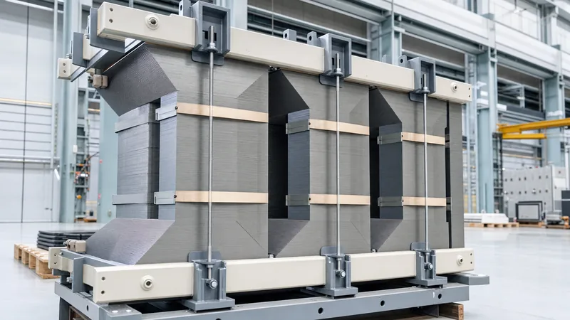
The structure of a transformer core consists of vertical sections called limbs or legs, horizontal connecting sections termed yokes, mechanical clamping structures, and interlaminar insulation. Windings are mounted concentrically around the limbs, while the yokes close the magnetic circuit, providing a continuous return path for the alternating magnetic flux generated under operational excitation.
Depending on physical layout and phase arrangements, transformer designs generally employ either core-type or shell-type structural topologies:
- Core-type construction: Windings surround the laminated core limbs. In a standard three-phase, three-limb core-type design, each limb carries both the low-voltage (LV) and high-voltage (HV) windings of one phase. This structure simplifies winding insulation and cooling duct placement, making it standard for high-voltage power applications examined in our transmission transformer engineering guide.
- Shell-type construction: The laminated magnetic core surrounds and encloses the windings. Shell-type designs offer superior mechanical bracing against severe radial short-circuit forces and provide a natural low-reluctance return path, making them well-suited for high-current industrial furnace transformers and specific rail applications.
- Five-limb core-type construction: Used extensively in large three-phase units, this variant adds two unwound outer return limbs. These return paths reduce total frame height for road transport clearance and accommodate zero-sequence flux during unbalanced grid faults without causing stray flux heating inside structural steel tanks.
What Is the Core of Transformer Material?
The primary core of transformer material is cold-rolled grain-oriented (CRGO) silicon electrical steel, engineered with anisotropic magnetic properties aligned along the rolling direction. Adding 3.0% to 3.4% silicon increases electrical resistivity to approximately 45 to 50 micro-ohm-centimetres, which suppresses parasitical eddy currents while preserving high magnetic saturation induction above 1.9 Tesla.
Advanced magnetic core materials have evolved to meet stringent international energy efficiency mandates, such as EU Ecodesign EN 50588-1 and US DOE 10 CFR Part 431. The choice of core material governs core loss (measured in watts per kilogram at a specific flux density, such as 1.7 T at 50 Hz or 60 Hz), total ownership cost, and equipment dimensions. The primary materials utilised across modern power distribution include:
- Conventional CRGO Steel (e.g., M4, M5): Standard grade featuring Goss texture orientation, providing stable performance at peak operating flux densities around 1.60 T to 1.65 T.
- High-Permeability CRGO (Hi-B): Formulated with aluminium nitride inhibitors to yield superior crystal grain alignment. Hi-B grades allow operational flux densities between 1.70 T and 1.75 T with lower magnetising currents and reduced magnetostriction.
- Domain-Refined CRGO: Processed using surface laser scribing or mechanical etching to divide wide magnetic domains into narrower domains, reducing anomalous eddy current losses by an additional 8% to 15%.
- Amorphous Metal Alloys: Metallic glass ribbons produced by ultra-rapid cooling (10^6 degrees Celsius per second) of iron-boron-silicon alloys. Lacking a crystalline lattice, amorphous materials feature exceptionally low coercive force, yielding no-load losses up to 70% lower than standard silicon steel, although their lower saturation point (around 1.56 T) necessitates a physically larger core cross-section.
Comparing Core Materials: Technical Specifications and Losses
Evaluating core materials requires comparing specific magnetic losses, nominal operating flux densities, stacking factors, and magnetostriction characteristics. The table below outlines technical metrics across industrial magnetic materials tested under standard IEC 60404-2 Epstein frame conditions at 50 Hz.
| Material Grade | Nominal Thickness (mm) | Specific Loss at 1.5 T (W/kg) | Specific Loss at 1.7 T (W/kg) | Saturation Induction (T) | Stacking Factor (%) |
|---|---|---|---|---|---|
| Standard CRGO (M4) | 0.27 | 0.85 - 0.92 | 1.25 - 1.35 | 2.00 - 2.03 | 96.0% |
| High-Permeability (Hi-B) | 0.27 | 0.72 - 0.80 | 1.05 - 1.15 | 2.02 - 2.05 | 96.5% |
| Laser Domain Refined | 0.23 | 0.58 - 0.65 | 0.82 - 0.92 | 2.02 - 2.05 | 95.5% |
| Ultra-Thin Domain Refined | 0.20 | 0.50 - 0.56 | 0.72 - 0.80 | 2.02 - 2.05 | 94.5% |
| Fe-Si-B Amorphous Metal | 0.025 | 0.18 - 0.22 | N/A (Saturates) | 1.56 - 1.58 | 84.0 - 86.0% |
Selection depends heavily on the project loss capitalisation formula (often designated as A-values for no-load loss and B-values for load loss). Where utilities capitalise no-load losses at over 6,000 to 10,000 USD per kilowatt, ultra-thin domain-refined steels or amorphous cores provide clear commercial advantages over the thirty-year asset operational life.
How Are Transformer Cores Manufactured and Assembled?
Manufacturing a transformer core involves precision lamination cutting, stacking with step-lap joints, rigid mechanical clamping, and single-point grounding to mitigate stray eddy currents. Maintaining tight dimensional tolerances prevents interlaminar insulation abrasion and excessive air gaps at joint interfaces.
- Slitting and De-coiling: Master coils of grain-oriented electrical steel are uncoiled and slit into specified lamination widths using tungsten-carbide rotary shears, maintaining edge burr heights below 0.01 mm to eliminate electrical shorting between stacked sheets.
- Automated Cut-to-Length and Mitring: High-speed automated shear lines cut individual plates with 45-degree mitred ends. Automated lines introduce progressive offsets of 1.0 to 5.0 mm between successive layers to form step-lap multi-layer joint profiles.
- Lamination Stacking: Laminations are stacked horizontally on rigid assembly tables. Step-lap joints stagger the butt joints across 5 to 7 layers, ensuring magnetic flux transitions smoothly from limb to yoke without saturating local steel edges.
- Core Clamping: Heavy-duty structural steel channels, clamping plates, and non-magnetic stainless steel or resin-impregnated glass tape bands secure the limbs and yokes. Clamping pressures are maintained between 0.30 and 0.50 MPa across the core face to minimise vibration without exceeding material compressive limits.
- Core Earthing: The entire magnetic stack is electrically bonded and connected to the tank via a single, removable earthing bridge (often isolated with a 2 kV bushing for field testing), preventing capacitive charging while eliminating circulating earth loops.
Core clamping directly influences performance in both liquid-filled units and solid-cast installations, such as those evaluated in our dry-type transformer guide, where resonant mechanical vibrations dictate total substation acoustic ratings.
Understanding Core Losses: Hysteresis, Eddy Currents, and Stray Flux
Core losses, also designated as no-load or iron losses, represent the continuous power dissipated in the magnetic circuit whenever the transformer is energised, irrespective of connected customer load. Total core loss is calculated as the sum of hysteresis loss, classical eddy current loss, and anomalous (excess) eddy current loss:
P_core = P_hysteresis + P_eddy + P_excess
Hysteresis loss occurs due to the energy required to continuously reorient magnetic domains within the ferromagnetic crystal lattice twice per electrical cycle. It is calculated using the empirical Steinmetz equation:
P_h = k_h * f * (B_max)^n
Here, k_h represents the material hysteresis coefficient, f represents operating frequency (Hz), B_max is peak magnetic flux density (T), and the Steinmetz exponent n typically ranges between 1.6 and 2.0 for modern electrical steels.
Eddy current loss results from circular circulating currents induced within the conductive steel by the alternating magnetic field. Classical eddy loss per unit mass is defined mathematically as:
P_e = (pi^2 * f^2 * d^2 * B_max^2) / (6 * rho * gamma)
In this relationship, d represents lamination thickness (m), rho is electrical resistivity (ohm-metres), and gamma is material density (kg/m^3). Because eddy current dissipation scales with the square of lamination thickness (d^2), reducing steel thickness from 0.30 mm to 0.23 mm reduces classical eddy current losses by approximately 41%.
Proper diagnostic evaluation and verification of factory no-load loss guarantees require calibrated test instruments and voltage-ratio checks, as detailed in our guide on how to test a transformer.
Core Noise, Magnetostriction, and Resonance Control
Transformer core noise is primarily generated by magnetostriction, an intrinsic phenomenon where ferromagnetic materials physically expand and contract along the direction of magnetic flux during every half-cycle of alternating current. Operating at 50 Hz, this dimensional fluctuation generates a base acoustic vibration frequency of 100 Hz, accompanied by higher harmonic overtones at 200 Hz, 300 Hz, and 400 Hz.
In addition to magnetostriction, magnetic clamping forces across the step-lap joints produce inter-lamination Maxwell forces that can drive excessive acoustic emission if mechanical clamping is non-uniform. Controlling core noise to comply with NEMA TR-1 or IEC 60076-10 acoustic standards requires specific engineering measures:
- Limiting nominal core operating flux density below 1.65 T for installations adjacent to commercial or residential spaces, avoiding the exponential rise in magnetostriction that occurs near magnetic saturation.
- Using high-permeability, laser-scribed electrical steels that exhibit lower linear magnetostrictive strain (lambda values below 1.0 x 10^-6).
- Applying uniform hydraulic clamping across all core limbs using pre-torqued tie-rods, non-magnetic fiberglass banding, and anti-vibration damping pads under the bottom yoke feet.
- Isolating the active core and coil assembly from the main tank using resilient elastomeric or spring-type isolation dampeners to prevent acoustic structural resonance through tank walls.
Next Steps: Specifying and Sourcing
When specifying a high-performance transformer core for utility, commercial, or heavy industrial applications, consult early with the engineering team to review loss capitalisation parameters and operational profiles. Prepare single-line diagrams, target system voltages, grid frequency (50 Hz or 60 Hz), maximum acceptable no-load loss limits, sound pressure criteria (dB(A)), and dimensional footprint constraints.
Review our factory manufacturing lines for power transformers, explore options for oil-immersed transformers, or inspect heavy-duty dry-type transformers built to IEC and IEEE standards. Submit your project requirements and loss formulas to our design specialists via the transformer quotation page or reach out directly through our engineering contact portal to secure an optimised technical proposal.
Frequently asked questions
What is the primary function of a transformer core?
The primary function of a transformer core is to provide a highly permeable, low-reluctance magnetic path that concentrates magnetic flux between the primary and secondary windings. This enables efficient electromagnetic power transfer at minimal excitation current.
Why is a transformer core laminated instead of solid?
A transformer core is laminated into thin, insulated sheets to interrupt continuous electrical paths, drastically reducing eddy current losses. Solid iron cores would permit massive internal circulating currents, causing severe thermal runaway and excessive power waste.
What causes core saturation in a transformer?
Core saturation occurs when the applied voltage and frequency demand a magnetic flux density exceeding the material's magnetic carrying capacity. When saturated, magnetic permeability drops rapidly toward the level of air, driving up excitation current, operating temperature, and acoustic noise.
What is the difference between core-type and shell-type transformers?
In a core-type transformer, the conductive windings physically surround the vertical laminated core limbs. In a shell-type transformer, the laminated magnetic core encloses the primary and secondary windings, offering enhanced bracing against severe short-circuit stresses.
How does step-lap mitred joint construction improve efficiency?
Step-lap mitred joints cut lamination ends at 45-degree angles and overlap successive layers across progressive offset steps. This geometry eliminates direct vertical air gaps, smoothing the flux transition between limbs and yokes to decrease no-load losses and acoustic vibration.
Tags: transformer core core of transformer material structure of a transformer magnetic core no-load losses


