Key takeaways
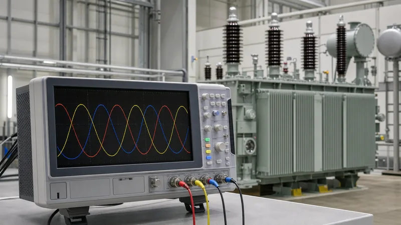
- A symmetrical 3 phase wave consists of three sinusoidal alternating voltages of equal frequency and amplitude displaced from each other by exactly 120 electrical degrees (2π/3 radians).
- Line-to-line voltage in a balanced star system is mathematically equal to the line-to-neutral phase voltage multiplied by √3 (approximately 1.732) and leads the phase voltage by 30 degrees.
- The instantaneous sum of balanced voltages across all three conductors at any given instant in a 3 phase waveform is identically zero.
- Transformer winding connections directly shift the phase angle of the 3 phase wave, such as a Dyn11 transformer advancing secondary phase angles by 30 degrees relative to the primary.
- Balanced three-phase waveforms transfer constant, non-pulsating instantaneous power to symmetrical loads, minimising mechanical vibration in electric motors and generators.
Quick answer: A 3 phase wave is a polyphase alternating current electrical system where three sinusoidal waveforms of identical frequency and peak amplitude are separated by a constant phase displacement of 120 electrical degrees (one-third of a full cycle). This spatial and temporal displacement enables balanced, constant instantaneous power delivery, eliminates the need for an oversized neutral conductor, and naturally generates a rotating magnetic field in induction machines.
Understanding the properties of a 3 phase wave is foundational for power distribution engineers, substation designers, and plant operators. Whether configuring medium-voltage distribution networks or commissioning industrial power infrastructure detailed in our 3-phase transformer buyer guide, wave characteristics dictate voltage relationships, vector grouping, fault clearing, and harmonic mitigation across international networks operating at 50 Hz or 60 Hz.
Anatomy of a 3 Phase Waveform: Mathematical Derivation and Phase Displacement
A balanced 3 phase waveform is generated by three separate armature coils physically arranged at 120-degree spatial intervals within a synchronous generator stator. As the rotor's magnetic flux cuts across each winding at angular frequency ω (where ω = 2πf rad/s), it induces three instantaneous electromotive forces (EMF) described by time-domain sinusoidal equations:
vA(t) = Vm sin(ωt)
vB(t) = Vm sin(ωt - 120°) = Vm sin(ωt - 2π/3)
vC(t) = Vm sin(ωt - 240°) = Vm sin(ωt + 120°) = Vm sin(ωt + 2π/3)
Here, Vm represents the peak voltage amplitude, and f denotes the system frequency (50 Hz under IEC standards, producing a period of 20 ms, or 60 Hz under IEEE/ANSI standards, with a 16.67 ms period). One of the most vital mathematical properties of the 3 phase wave is that the instantaneous sum of all three phases at any instant t equals zero:
vA(t) + vB(t) + vC(t) = 0
Because the sum equals zero in a balanced star (wye) configuration, the neutral conductor carries zero return current. This allows system designers to downsize or eliminate return conductors, delivering up to 73.2% more power than a single-phase circuit using only 1.5 times the copper or aluminium conductor mass. Furthermore, the instantaneous total power delivered by a balanced 3 phase waveform remains constant over time (Ptotal = 3 × VRMS × IRMS × cos φ), preventing torque pulsations in heavy industrial rotating machinery.
Phase Voltage vs Line Voltage Relationships
Phase voltage represents the potential difference measured across an individual phase winding, whereas line voltage represents the potential difference between any two line conductors. In a star-connected system, the phase voltages (VAN, VBN, VCN) originate at a common star point or neutral terminal. The line-to-line voltage (VAB) is obtained via phasor subtraction: VAB = VAN - VBN.
Using trigonometric resolution on the complex phasor plane:
VAB = VLN ∠0° - VLN ∠-120° = VLN [1 - (-0.5 - j√3/2)] = VLN [1.5 + j√3/2] = √3 × VLN ∠30°
This derivation proves two essential tenets of three-phase power networks: the line-to-line RMS magnitude is precisely √3 (approximately 1.73205) times the phase-to-neutral RMS magnitude, and the line voltage waveform leads the corresponding phase voltage waveform by 30 electrical degrees. For deeper mathematical breakdowns of system voltages, refer to our guide on 3 phase voltage calculations. Conversely, in a delta-connected configuration, the line voltage is directly equal to the phase voltage (VLL = VLN), while the line current is √3 times the phase current and lags the phase current by 30 degrees.
How Transformer Vector Configurations Alter the 3 Phase Waveform
Transformer winding configurations directly alter the angular displacement between primary and secondary three-phase waveforms according to standard vector groups defined in IEC 60076-1. The phase angle displacement is expressed using clock notation, where each hour represents a 30-degree phase shift of the low-voltage (LV) wave relative to the high-voltage (HV) wave positioned at 12 o'clock (0 degrees).
In standard commercial and industrial distribution, delta-star transformers such as the Dyn11 configuration are widely specified. As detailed in our engineering review of delta wye transformer wiring, the high-voltage winding is connected in delta (D), the low-voltage winding is connected in star with an accessible neutral (yn), and the secondary phase wave leads the primary phase wave by 30 degrees (11 o'clock position, or +30°). If the transformer is wired as Dyn1, the secondary waveform lags the primary waveform by 30 degrees (1 o'clock position, or -30°).
Engineers must guarantee identical vector displacement when synchronising or paralleling units such as power transformers or dry-type transformers on a common busbar. Connecting two units with mismatched vector configurations (for example, attempting to parallel a Dyn11 unit with a Dyn5 unit, which has a 150-degree displacement) produces an immediate, catastrophic line-to-line short circuit governed by the phase voltage difference across their leakage impedances.
Step-by-Step: How to Measure and Verify a 3 Phase Waveform on Site
Field verification of a 3 phase waveform confirms correct phase rotation, identifies voltage imbalance, and validates zero displacement before energising sensitive equipment. Technicians should execute the following test procedure using a calibrated digital storage oscilloscope (DSO) or a high-accuracy power quality analyser:
- Isolate and Lock Out Power: De-energise the switchgear cubicle, apply Lockout/Tagout (LOTO) protocols according to NFPA 70E or IEC 61482, and verify the absence of nominal voltage using a verified high-voltage detector.
- Connect Isolated Voltage Attenuators: Attach three high-voltage differential probes to terminals L1 (Phase A), L2 (Phase B), and L3 (Phase C), with the common reference lead bonded to the system star point or ground terminal. Never use non-isolated single-ended oscilloscope grounds on three-phase lines.
- Configure Timebase and Triggering: Set the instrument timebase to 5 ms/div (for 50 Hz networks) or 2 ms/div (for 60 Hz networks) to display 2 to 3 complete cycles across the display screen. Select Phase A as the internal trigger source.
- Verify Phase Sequence and Angular Displacement: Measure the time delta (Δt) between zero-crossings of Phase A and Phase B. In a healthy 50 Hz network, Phase B must cross zero going positive exactly 6.67 ms after Phase A (representing 120°). Phase C must cross zero 13.33 ms after Phase A (240°).
- Calculate Voltage Unbalance Factor (VUF): Measure RMS values across L1, L2, and L3. Calculate unbalance percentage using IEC 61000-4-30: the ratio of negative-sequence voltage to positive-sequence voltage must remain below 2% to avoid motor overheating.
- Document Waveform Distortion: Capture waveform screenshots and quantify Total Harmonic Distortion (THDV), verifying compliance with IEEE 519 (typically less than 5.0% for distribution voltages up to 69 kV).
Harmonic Distortion and Power Quality Effects on the 3 Phase Wave
Harmonic distortion alters the pure sinusoidal geometry of the 3 phase wave when non-linear loads draw current in sharp pulses rather than continuous waves. Common non-linear loads include variable frequency drives (VFDs), uninterruptible power supplies (UPS), silicon-controlled rectifiers, and electric vehicle charging stations. These non-linear currents generate harmonic voltages across grid impedances, distorting the nominal wave profile.
Harmonic orders are mathematically divided into sequence components that behave differently within a three-phase architecture:
- Positive-Sequence Harmonics (4th, 7th, 10th...): Rotate in the same direction as the fundamental 3 phase waveform, generating forward rotational magnetic fields that can cause thermal stress in synchronous motors.
- Negative-Sequence Harmonics (2nd, 5th, 8th...): Rotate in the reverse direction relative to the fundamental wave, exerting counter-torque on induction motor shafts and accelerating rotor bearing degradation.
- Zero-Sequence Harmonics (3rd, 9th, 15th... / Triplens): Possess zero relative phase displacement between phases (they are in phase with one another). In a star network, triplen harmonic currents do not cancel at the neutral point; instead, they sum additively in the neutral conductor, frequently causing neutral conductor currents to exceed 173% of full-load phase currents.
Specifying distribution units such as oil-immersed transformers with delta primary windings allows triplen currents to circulate harmlessly within the closed delta mesh, attenuating zero-sequence harmonic transfer into upstream transmission feeders.
Engineering Characteristics Across Polyphase Wave Configurations
To select appropriate generation, transformation, and distribution apparatus, electrical engineers contrast the operating parameters of various alternating current wave regimes. The following table summarises key mathematical and structural characteristics comparing single-phase, split-phase, and three-phase waveforms.
| System Configuration | Conductors Required | Wave Phase Shift (Degrees) | RMS Voltage Ratio (Line-Line / Line-Neutral) | Instantaneous Power Characteristics | Typical Application & Standards |
|---|---|---|---|---|---|
| Single-Phase 2-Wire | 2 (L + N) | 0° (Single waveform) | 1.0 (No Line-to-Line) | Pulsating at 2× fundamental frequency (drops to zero) | Residential lighting, domestic appliances (<10 kVA) |
| Split-Phase 3-Wire | 3 (L1 + L2 + N) | 180° displacement | 2.0 × VLN | Pulsating at 2× fundamental frequency | North American residential (120/240 V, ANSI C84.1) |
| 3-Phase 3-Wire (Delta) | 3 (L1 + L2 + L3) | 120° displacement | 1.0 (VLL = VLN) | Constant, non-pulsating under balanced conditions | Industrial motor feeders, MV distribution (IEC 60038) |
| 3-Phase 4-Wire (Star/Wye) | 4 (L1 + L2 + L3 + N) | 120° displacement | √3 ≈ 1.732 × VLN | Constant, non-pulsating under balanced conditions | Commercial distribution (400/230 V, 480Y/277 V) |
As evident from the table, four-wire star distribution provides the greatest operational flexibility by simultaneously supplying single-phase phase-to-neutral loads and high-capacity three-phase motor loads from a single substation installation.
Next steps: specifying and sourcing
When specifying distribution substations, skid-mounted packages, or replacement transformers for three-phase installations, engineers must evaluate exact wave parameters. Prepare technical requirements including rated system voltage (HV/LV), frequency (50 Hz or 60 Hz), vector group (such as Dyn11 or YNd11), short-circuit impedance percentage (%Z), and anticipated total harmonic distortion.
Explore our engineering range of power transformers and rugged oil-immersed transformers engineered in strict accordance with IEC 60076, IEEE C57, and ISO 9001 quality benchmarks. To submit site requirements, confirm vector matching, or obtain full factory-certified documentation, request a technical quotation or communicate directly with our engineering team via our contact page.
Frequently asked questions
Why is a 3 phase wave separated by 120 degrees?
A 3 phase wave is separated by 120 degrees because 120 degrees represents the optimal symmetrical division of a full 360-degree electrical circle among three phases. This specific geometric displacement ensures that the instantaneous sum of voltages is zero, balances mechanical torque in generators, and maintains constant non-pulsating power delivery.
What is the difference between single-phase and 3 phase waveforms?
A single-phase waveform uses one alternating sinusoidal voltage that passes through zero twice per cycle, causing delivered instantaneous power to pulse. A 3 phase waveform combines three overlapping sinusoidal voltages displaced by 120 degrees, producing a continuous, non-zero total power output and creating a rotating magnetic field in electric motors.
How do you calculate instantaneous voltage in a 3 phase wave?
Instantaneous voltage is calculated using the sinusoidal function v(t) = Vm sin(ωt + θ), where Vm is the peak voltage amplitude, ω is angular frequency (2πf), and θ is the phase angle offset. For Phases A, B, and C, θ corresponds to 0 degrees, -120 degrees, and +120 degrees (or -240 degrees) respectively.
Does a 3 phase wave have zero voltage at any point in time?
Individual phase conductors cross through zero volts twice every full cycle, but the overall 3 phase system never drops to zero total power. Because the waveforms are displaced by 120 degrees, when one phase is passing through zero, the remaining two phases are active at opposite polarities, maintaining steady system power.
What happens to the 3 phase wave during a phase-to-ground fault?
During a single phase-to-ground fault, the voltage waveform of the faulted phase collapses towards zero while the remaining healthy phase waveforms may rise to line-to-line voltage levels in ungrounded networks. The symmetrical 120-degree displacement is distorted, introducing severe negative-sequence and zero-sequence current components that trip protective relays.
Tags: 3 phase wave 3 phase waveform transformer configurations electrical engineering power quality


