Key takeaways
- A delta y transformer connects the primary winding in a closed delta mesh (three-wire) and the secondary winding in a four-wire wye configuration with an accessible neutral.
- The standard secondary line-to-line voltage in a wye system is 1.732 times the line-to-neutral voltage, enabling simultaneous 480V three-phase and 277V single-phase, or 400V and 230V power distribution.
- Delta primary windings trap triplen harmonics (3rd, 9th, 15th) as circulating zero-sequence currents, preventing harmonic distortion from flowing back onto the medium-voltage utility supply.
- Standard industrial delta wye transformer designs introduce a 30-degree electrical phase shift, designated as Dyn11 (30-degree lead) under IEC 60076 or Dyn1 (30-degree lag) under IEEE C57.12.00 standards.
- Specifying a delta-wye unit requires defining kVA rating, primary and secondary voltages, basic lightning impulse insulation level (BIL), impedance percentage (%Z), and core loss limits.
Quick answer: A delta y transformer (or delta-wye transformer) is a three-phase electrical machine featuring primary windings connected in a closed delta circuit and secondary windings connected in a wye (star) configuration. It provides a stable, four-wire secondary distribution system with a groundable neutral point while blocking triplen harmonic currents from entering the medium-voltage utility grid.
In industrial and utility electrical infrastructure, the delta-wye arrangement serves as the global standard for step-down distribution substations. Connecting medium-voltage distribution feeders directly to low-voltage customer switchboards requires careful management of unbalanced single-phase loads, ground fault paths, and harmonic distortion. For a complete overview of three-phase transformation principles, consult our 3-phase transformer buyers guide.
How a Delta Wye Transformer Operates
A delta wye transformer operates by converting three-phase primary currents across line-to-line winding arrangements into a secondary system referenced to a common neutral point. The primary side uses three winding phases connected head-to-tail in an equilateral triangle. Because there is no primary neutral conductor, the primary side accepts standard three-wire medium-voltage distribution lines, typically rated at 11 kV, 22 kV, 13.8 kV, or 34.5 kV.
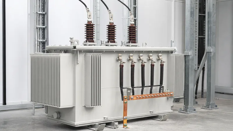
On the secondary side, one end of each phase winding connects to a common star point (neutral), while the opposite ends connect to the line terminals (X1, X2, X3). Grounding this central neutral point establishes a stable reference for the entire low-voltage network. This allows facilities to power heavy three-phase industrial motors while simultaneously feeding single-phase lighting and office branch circuits from line-to-neutral connections without creating neutral voltage drift. To explore connection schematics in depth, refer to our detailed guide on the delta wye transformer diagram.
Voltage Calculations: Wye vs Delta Wiring
Understanding wye vs delta wiring requires calculating the relationship between phase voltages (across individual coils) and line voltages (between external terminals). In a delta-connected primary winding, the line-to-line voltage equals the phase voltage (V_line = V_phase), meaning each primary coil withstands full system line voltage, while line current is the vector sum of adjacent phase currents (I_line = √3 × I_phase).
Conversely, in a secondary wye transformer winding, each individual phase winding carries full line current (I_line = I_phase), but the line-to-line voltage is √3 (approximately 1.732) times higher than the line-to-neutral voltage. For instance, in an IEC standard 400 V low-voltage system:
V_LN = 400 V / √3 = 230.94 V
In an ANSI/IEEE 480 V industrial facility:
V_LN = 480 V / √3 = 277.13 V
Engineers can examine further technical details regarding phase relationships in our technical brief on 3-phase phase to phase voltage calculations.
Delta vs Wye Transformer Configurations Compared
When comparing delta vs wye transformer configurations, engineers must evaluate neutral availability, phase displacement, harmonic mitigation, and ground-fault behaviour. The table below summarises the mechanical and electrical trade-offs between standard configurations across industrial networks.
| Configuration | Primary Wires | Secondary Wires | Neutral Available | Triplen Harmonic Trapping | Typical Application |
|---|---|---|---|---|---|
| Delta-Wye (Dyn) | 3 | 4 | Yes (Secondary) | Yes (Trapped in Delta) | Standard distribution substations, commercial facilities |
| Wye-Delta (Yd) | 4 or 3 | 3 | Yes (Primary) | Yes (Secondary Delta) | Generator step-up (GSU), high-voltage transmission |
| Delta-Delta (Dd) | 3 | 3 | No | Yes (Both sides) | Industrial motor plants, ungrounded process power |
| Wye-Wye (Yy) | 4 | 4 | Yes (Both sides) | No (Requires tertiary) | Interconnecting transmission grids at similar voltage |
| Wye-Delta-Wye | 4 | 4 | Yes (Both sides) | Yes (Tertiary Delta) | High-voltage substations with tertiary station service |
Phase Displacement and Vector Groups in a Delta Y Transformer
A delta y transformer introduces an inherent 30-degree electrical phase angle shift between the primary and secondary line voltages due to the geometry of delta-to-wye vector relationships. In electrical schematics conforming to IEC 60076-1, this phase relationship is codified using vector group nomenclature such as Dyn11 or Dyn5.
In a Dyn11 unit, the secondary line voltage leads the primary line voltage by 30 degrees (representing 11 o'clock on a clock face where each hour equals 30 degrees). In North American IEEE C57.12.00 practice, the standard distribution configuration is a 30-degree lag, functionally equivalent to a Dyn1 designation. When synchronising or paralleling two transformers onto a common low-voltage busbar, identical vector groups, phase angles, and short-circuit impedances (%Z) are strictly required to avoid catastrophic circulating short-circuit currents. A detailed analysis of phase displacement is covered in our resource on transformer vector groups explained.
Harmonic Management and the Wye Delta Wye Transformer
The delta winding in a delta-wye configuration acts as an automatic filter for zero-sequence triplen harmonics (3rd, 9th, 15th, etc.) produced by non-linear loads such as variable frequency drives (VFDs), uninterruptible power supplies (UPS), and rectifier systems. Because triplen harmonics are in-phase with each other across all three legs, they sum at the delta junction and circulate harmlessly within the closed delta loop as heat, rather than propagating back into the upstream grid.
However, when utility transmission planners require grounded wye connections on both primary and secondary terminals for system grounding, third-harmonic flux can distort the core flux and overheat the tank. To resolve this without losing the wye-wye connection, engineers specify a wye delta wye transformer (or wye-wye with delta tertiary). In this design, a third, ungrounded delta winding (tertiary) is embedded within the core to trap zero-sequence harmonic currents and stabilize the neutral potential during ground faults.
Step-by-Step Procedure for Commissioning and Phasing Checks
Commissioning a delta y transformer requires rigorous verification of winding ratios, polarity, and phasing before closing the low-voltage isolator into energized switchgear.
- Perform cold insulation resistance tests using a 2.5 kV or 5 kV DC megohmmeter between primary-to-ground, secondary-to-ground, and primary-to-secondary windings to confirm insulation integrity.
- Measure the turns ratio across all off-circuit tap changer (OCTC) positions with a three-phase turns ratio tester, verifying that measured ratios align within ±0.5% of nameplate values per IEEE C57.12.90 or IEC 60076-1.
- Conduct winding resistance testing across all phases with a micro-ohmmeter, verifying phase balance within 2% to ensure no loose internal crimps or broken tap-changer contacts.
- Energise the primary side at rated medium voltage while leaving the secondary circuit breaker open and isolated.
- Verify secondary phase-to-neutral voltages (e.g., nominal 230 V or 277 V) and phase-to-phase voltages (e.g., 400 V or 480 V) across terminals X1, X2, X3, and X0 with a calibrated true-RMS digital multimeter.
- Perform a phase rotation test using a rotation meter connected to the secondary phase terminals to ensure clockwise (A-B-C) sequence matching the facility busbar.
- If paralleling with an existing source, perform voltmeter checks across corresponding phases (Phase A1 to A2, B1 to B2, C1 to C2); each reading must show near-zero volts before closing the tie-breaker.
Next steps: specifying and sourcing
When specifying a delta-wye distribution transformer for infrastructure, industrial, or commercial projects, prepare a comprehensive data sheet outlining your operating parameters. Ensure your procurement requisition states rated capacity in kVA or MVA, nominal primary and secondary voltages, primary insulation BIL (e.g., 95 kV BIL for 15 kV class), cooling class (ONAN, ONAF, or AN/AF), tap changer range (±2 × 2.5%), and target percentage impedance (%Z). Review our engineered oil-immersed transformers or fire-resistant dry-type transformers to evaluate enclosure and cooling options. To discuss project-specific vector groups, custom loss evaluations, or short-circuit requirements, submit your engineering single-line diagram directly to our technical team through our transformer quotation portal.
Frequently asked questions
Why is a delta y transformer preferred for distribution systems?
A delta y transformer is preferred because it establishes a four-wire system with an accessible secondary neutral. This allows simultaneous supply of single-phase and three-phase loads while isolating the primary utility lines from secondary zero-sequence unbalance and triplen harmonics.
What is the difference between delta and wye transformer connections?
In a delta connection, three phase windings form a closed loop with no neutral, where line voltage equals phase voltage. In a wye connection, three windings meet at a common central neutral point, making line-to-line voltage equal to 1.732 times line-to-neutral voltage.
What causes the 30-degree phase shift in a delta wye transformer?
The 30-degree phase shift occurs because secondary line voltages are derived from line-to-neutral vector combinations of individual wye windings, whereas primary line voltages span directly across line-to-line delta windings. This vector geometry inherently shifts output voltages by ±30 degrees.
Can you back-feed a delta wye transformer?
Back-feeding a delta wye transformer by energising the wye secondary as a step-up primary is electrically possible but poses severe operational and protection hazards. Unless specifically engineered for back-feeding, floating the wye neutral or improper grounding can lead to extreme overvoltages and core saturation during ground faults.
What is the purpose of a wye delta wye transformer?
A wye delta wye transformer utilizes a primary grounded wye, a secondary grounded wye, and an internal buried delta tertiary winding. The delta tertiary traps triplen harmonic currents, prevents neutral voltage instability, and balances phase-to-ground faults without exposing delta terminals externally.
How does a delta y transformer handle unbalanced loads?
Unbalanced single-phase loads return through the secondary neutral conductor to the wye star point. The primary delta winding distributes the corresponding single-phase ampere-turns across two primary phases, maintaining balanced voltage regulation and preventing neutral point displacement.
Tags: delta y transformer delta wye transformer wye transformer delta vs wye transformer wye delta wye transformer


