Key takeaways
- A 480V to 240V transformer converts three-phase or single-phase 480V distribution voltages down to 240V or split-phase 120/240V for commercial and light industrial loads.
- Dual-winding secondaries labelled X1 to X4 deliver 240V when coils are connected in series (X2 jumpered to X3) and 120V when connected in parallel (X1 to X3, X2 to X4).
- Per NEC Article 450.3(B), low-voltage transformers with primary currents of 9 amperes or more require primary overcurrent protection rated at no more than 125% of rated current, unless secondary protection is provided.
- Standard industrial dry-type low-voltage transformers comply with NEMA standards and UL 1561, typically operating with Class 220 insulation systems and an 80°C, 115°C, or 150°C temperature rise.
- Full-load primary current for a single-phase 480V step-down unit equals rated apparent power in volt-amperes divided by 480V (I = VA / 480).
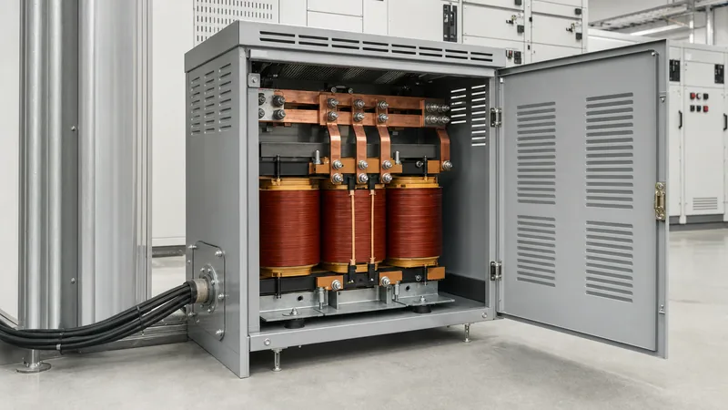
Quick answer: A 480V to 240V transformer is a low-voltage step-down transformer designed to convert 480V industrial supply power to 240V or split-phase 120/240V for operating machinery, heating circuits, motors, and auxiliary building services. Available in single-phase and three-phase designs, these transformers use dual secondary windings to provide flexible output voltages while isolating branch circuits from grid-side disturbances.
Industrial facilities in North America and overseas sites supplied by 480V delta or wye feeds frequently require lower distribution voltages to feed single-phase machinery, control enclosures, HVAC equipment, and workshop services. Applying a dedicated 240v transformer eliminates the expense of running secondary utility services into the facility. Choosing the correct unit requires understanding coil configurations, impedance percentages, inrush current characteristics, and overcurrent protection requirements mandated by standards such as NFPA 70 (NEC) Article 450 and IEEE C57.12.00.
Proper application also demands an understanding of when to specify a general-purpose dry-type unit versus an encapsulated or oil-immersed configuration. Engineers evaluating plant-wide transformation schemes should review our low-voltage transformer selection guide to understand broader system architecture before finalising individual unit ratings.
Single-Phase vs Three-Phase 480V to 240V Transformer Configurations
A 480V to 240V transformer is selected based on whether the downstream equipment requires a single-phase supply or balanced three-phase power. While heavy motor loads and industrial chillers frequently demand three-phase 240V delta or 208Y/120V systems, single-phase loads dominate small process machinery, electric heaters, and auxiliary panels.
A 480v single phase transformer steps down one phase pair from a 480V three-phase feeder (line-to-line) to deliver single-phase power. In contrast, a three-phase unit incorporates three sets of primary and secondary coils on a common laminated core. The winding connections dictate whether a neutral conductor can be derived. For single-phase installations, engineers often specify a single phase 480 to 120 240 transformer with split secondary windings, providing both 240V line-to-line for heating or motor circuits and 120V line-to-neutral for control equipment.
The table below outlines the structural and operational differences across standard configurations:
| Configuration | Primary Voltage (V) | Secondary Voltage (V) | Phase & Frequency | Typical Application |
|---|---|---|---|---|
| Single-Phase Split Secondary | 480 | 120/240 | 1-phase, 60 Hz | Control panels, machine tools, workshops |
| Three-Phase Delta-Delta | 480D | 240D | 3-phase, 60 Hz | Legacy motors, pump stations, process skids |
| Three-Phase Delta-Wye | 480D | 240Y/139 | 3-phase, 60 Hz | Mixed motor and lighting installations |
| Single-Phase Isolation | 480 | 240 | 1-phase, 50/60 Hz | Industrial ovens, dedicated resistance welders |
Where plant expansion requires individual branch isolation or isolated neutral conductors, specifying a single-phase transformer minimizes fault current exposure while keeping installation footprints compact.
Wiring a 480 to 120 240 Transformer: Series vs Parallel Secondary Coils
Terminal connections on a dual-secondary 480 to 120 240 transformer dictate whether the unit supplies 120V, 240V, or a simultaneous 120/240V three-wire system. The primary winding has two terminals, marked H1 and H2. The secondary comprises two electrically isolated 120V coils terminated at four lead points: X1, X2, X3, and X4.
To configure a 480 to 240 transformer single phase output, connect the secondary coils in series. This arrangement creates a single 240V circuit or a 120/240V split-phase 3-wire distribution system per the standard procedure:
- Verify isolation and lock out the 480V upstream feeder breaker in accordance with site safety protocols.
- Connect the two 480V incoming line conductors to primary terminals H1 and H2. Verify polarity markings on the terminal board.
- For a 240V two-wire output, install a copper jumper link between secondary terminals X2 and X3. Take the 240V output across terminals X1 and X4.
- For a 120/240V three-wire system, retain the series link between X2 and X3. Terminate the grounded neutral conductor onto the X2 to X3 junction, forming the system centre tap. Connect Line 1 to X1 and Line 2 to X4.
- For a 120V-only high-current output, connect the coils in parallel: jumper X1 to X3 (Line) and X2 to X4 (Neutral). Never link X2 to X4 while linking X1 to X2, as this creates a short circuit.
When establishing a 120/240V neutral, IEEE C57.12.70 rules require bonding the X2 to X3 centre point to the equipment grounding conductor and grounding electrode conductor at the secondary disconnecting means, establishing a Separately Derived System under NEC 250.30.
Step-by-Step Sizing Calculation for a 480V Single Phase Transformer
Sizing a single phase step down transformer requires determining the total connected load in kilovolt-amperes (kVA), applying the continuous-duty factor, and matching the calculated result to standard manufacturing kVA ratings. Undersizing leads to nuisance tripping and thermal degradation, while excessive oversizing elevates no-load core losses and increases inrush fault levels.
Consider an auxiliary machinery enclosure fed from a 480V distribution board with the following connected single-phase loads at 240V:
- Continuous motor and heating load: 16.0 kVA (continuous defined as 3 hours or more per NEC Article 100)
- Non-continuous auxiliary control loads: 4.5 kVA
- Anticipated future expansion margin: 15%
First, apply the 125% factor to continuous loads required by NEC Article 215.2 and Article 450:
Design Load (kVA) = (Continuous kVA × 1.25) + Non-Continuous kVA
Design Load = (16.0 × 1.25) + 4.5 = 20.0 + 4.5 = 24.5 kVA
Apply the 15% future growth allowance:
Total Target kVA = 24.5 × 1.15 = 28.18 kVA
Select the next standard dry-type rating from standard sizes (15, 25, 37.5, 50, 75 kVA). The next standard size is 37.5 kVA. Now, calculate the full-load amps (FLA) on the primary and secondary sides to determine conductor sizing and breaker settings:
Primary FLA (480V) = (37.5 kVA × 1000) / 480V = 78.13 A
Secondary FLA (240V) = (37.5 kVA × 1000) / 240V = 156.25 A
Where facility retrofits involve bidirectional power flows or stepping up 120V to higher levels, similar sizing methodologies apply; see our guide on industrial power system installation for complete protective device coordination procedures.
Thermal Ratings, Impedance, and NEC Protection Rules
Dry-type transformers stepping down 480V to 240V operate under distinct thermal and electrical stresses governed by NEMA standards and UL 1561. Standard units feature Class 220 insulation with winding temperature rises of 150°C, 115°C, or 80°C above an ambient temperature of 40°C. Specifying an 80°C or 115°C rise unit ensures lower winding loss, higher continuous overload capability (15% to 30% above nameplate without exceeding thermal limits), and extended operational life.
Overcurrent protection must comply with NEC Article 450.3(B) for transformers operating at 1000V nominal or less. Where protection is provided on the primary side only:
- If primary full-load current is 9 amperes or more, the primary overcurrent protection device (OCPD) rating must not exceed 125% of rated primary current. Where 125% does not correspond to a standard fuse or circuit breaker rating per NEC 240.6, rounding up to the next higher standard rating is permitted.
- Using our 37.5 kVA example (78.13 A primary FLA): 78.13 A × 1.25 = 97.66 A. The next standard breaker rating per NEC 240.6 is 100 A.
If secondary overcurrent protection is installed (set at no more than 125% of secondary FLA: 156.25 A × 1.25 = 195.3 A, permitting a 200 A secondary breaker), NEC Table 450.3(B) allows the primary protection device to be set up to 250% of primary FLA (78.13 A × 2.5 = 195.3 A, allowing a 200 A primary breaker). This configuration prevents nuisance tripping caused by high magnetic inrush currents, which can reach 10 to 12 times rated FLA during initial energisation.
Percent impedance (%Z) directly governs secondary short-circuit levels. Standard single-phase 480V to 240V transformers typically exhibit 3% to 5% impedance. The maximum available symmetrical fault current at the secondary terminals is calculated as:
Short-Circuit Current (I_sc) = Secondary FLA / (%Z / 100)
For a 37.5 kVA unit with 3.5% impedance: 156.25 A / 0.035 = 4,464 A. Downstream equipment must have an interrupting rating exceeding this prospective fault level.
Factory Specification Checklist for a 240 Volt Transformer
Specifying a reliable 240 volt transformer requires an unambiguous procurement sheet that captures environmental, electrical, and mechanical criteria before sending an RFQ to the factory. Incomplete specifications often lead to incorrect tap voltages, inadequate enclosure ratings, or sound levels unsuitable for indoor workspaces.
Engineers can incorporate the following checklist directly into purchasing documents for dry-type or oil-immersed low-voltage transformers:
- Power Rating: State continuous rating in kVA (e.g., 15, 25, 37.5, 50, 75, 100 kVA).
- Primary Voltage: 480V single-phase (or 480V three-phase delta), 60 Hz (or 50 Hz for international sites).
- Secondary Voltage: Dual 120/240V split secondary (series/parallel configurable) or fixed 240V.
- Voltage Taps: Specify full-capacity taps, standard arrangement: 2 × +2.5% and 2 × -2.5% (2-FCAN, 2-FCBN) to adjust for line voltage drops.
- Winding Material: Electrolytic copper or electrical-grade aluminium (copper preferred for tight dimensional constraints and severe vibratory environments).
- Insulation System: Class 220 insulation with 150°C, 115°C, or 80°C rise over 40°C ambient.
- Enclosure Protection: NEMA 1 / IP20 for clean indoor switchrooms; NEMA 3R / IP54 ventilated weather-resistant for outdoor or humid environments.
- Acoustic Noise Limit: Comply with standard NEMA sound levels (e.g., maximum 45 to 50 dBA for ratings up to 50 kVA).
- Electrostatic Shield: Include an earthed copper electrostatic shield between primary and secondary windings when feeding sensitive electronic equipment or variable frequency drive controllers.
For demanding environments such as dusty process areas or heavy industrial skids, explore factory-built dry-type transformers or robust outdoor oil-immersed transformers built to handle severe continuous duty cycles.
Next steps: specifying and sourcing
When preparing an RFQ for a 480V to 240V transformer, supply the engineering team with your load profile, operating environment, ambient temperature limits, and preferred enclosure rating. Our technical team manufactures custom-engineered dry-type and liquid-filled step-down transformers meeting IEC, IEEE C57, and UL requirements. Review our complete range of low-voltage and medium-voltage equipment on the dry-type transformer catalogue, or submit your single-line diagram and tender parameters directly through our transformer quotation page for rapid design support and commercial pricing.
Frequently asked questions
Can a 480V to 240V transformer be wired in reverse to step up voltage?
Yes, standard dry-type low-voltage transformers can be reverse-fed to step up 240V to 480V. However, the secondary winding becomes the primary, meaning inrush current will be significantly higher and standard taps will be on the load side rather than the source side. The primary overcurrent device must be sized to accommodate this elevated inrush.
How do you get 120V from a 480 to 240 transformer single phase?
To obtain 120V, use a unit with dual secondary windings (X1 to X4). Wire X2 and X3 in series to create a centre-tapped 120/240V system where voltage between either line (X1 or X4) and the centre tap equals 120V. Alternatively, jumper X1 to X3 and X2 to X4 in parallel for a high-current 120V-only output.
What is the difference between a 480V to 240V transformer and a 480V to 208V transformer?
A 480V to 240V transformer provides either single-phase 240V (or 120/240V split-phase) or three-phase 240V delta power. A 480V to 208V unit is almost always a three-phase delta-to-wye transformer delivering 208Y/120V, which provides three 120V phase-to-neutral circuits alongside 208V phase-to-phase for commercial loads.
What size breaker do I need for a 25 kVA 480V to 240V transformer?
A 25 kVA transformer has a primary full-load current of 52.1 A at 480V. Under NEC 450.3(B), sizing primary-only protection at 125% yields 65.1 A, permitting a standard 70 A circuit breaker. If secondary protection is installed, the primary breaker can be sized up to 250% (125 A) to prevent nuisance tripping during energisation.
Why does a 480V to 240V single phase transformer have four secondary terminals?
The four secondary terminals (X1, X2, X3, X4) represent two independent 120V secondary windings. Connecting X2 to X3 puts the coils in series for a 240V or split-phase 120/240V output, while connecting X1 to X3 and X2 to X4 puts the coils in parallel for maximum current capacity at 120V.
Tags: 480v to 240v transformer 240v transformer single phase step down transformer 480 to 120 240 transformer 480v single phase transformer


