Key takeaways
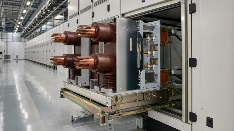
- A switchgear breaker serves as the primary dynamic interrupting device within an assembly, capable of making, carrying, and breaking rated normal currents as well as specified fault currents.
- Medium-voltage switchgear breakers predominantly rely on vacuum interrupters, which provide typical electrical endurances of 10,000 to 30,000 operations without contact degradation.
- Short-circuit making capacity must equal at least 2.5 times (for 50 Hz systems) or 2.6 times (for 60 Hz systems) the rated symmetrical breaking current under IEC 62271-100.
- A compliant switchgear room must provide dedicated clearance dimensions according to NFPA 70 Article 110.26 and IEC 61936-1 to enable safe racking and arc exhaustion.
- Routine verification requires contact resistance measurements below factory tolerances (typically under 35 micro-ohms) and breaker operating timing analysis across all three poles.
Quick answer: A switchgear breaker is a mechanical switching device capable of making, carrying, and interrupting currents under normal circuit conditions, as well as initiating and breaking specified abnormal currents, such as short circuits. It forms the core protective component of medium- and low-voltage electrical distribution assemblies.
In industrial distribution networks and substations, selecting the correct switchgear breaker determines whether downstream faults are cleared within tens of milliseconds or escalate into destructive arc flash events. Engineers must align breaker interrupting ratings, mechanism types, and protection interfaces with broader plant topologies. For comprehensive foundational context on assembly architecture, consult our guide to electrical switchgear systems.
Arc Quenching Technologies in the Modern Switchgear Breaker
Arc interruption technology dictates the size, endurance, and operational safety profile of every medium- and low-voltage switchgear breaker. When contacts part under load or fault conditions, an electric arc forms between the contact surfaces; the breaker must cool, de-ionise, and extinguish this plasma column at current zero to prevent re-ignition.
Modern power systems utilise three primary arc quenching mediums:
- Vacuum: The dominant medium for medium-voltage installations up to 40.5 kV. Arcs are extinguished within a sealed ceramic vacuum interrupter bottle at pressures below 10-5 Pa. As contacts separate, metal vapour sustains the arc until the first alternating-current zero, where the vapour condenses rapidly back onto the contact surfaces. For an in-depth review of interrupter mechanics, refer to our vacuum circuit breaker guide.
- Sulphur Hexafluoride (SF6): Used primarily in high-voltage installations and gas-insulated substations. SF6 exhibits superior dielectric strength and electronegativity, absorbing free electrons to form stable negative ions. However, environmental concerns and fluorinated gas regulations are accelerating the transition toward vacuum and alternative gas mixtures.
- Air Break: Common in low-voltage drawout breakers rated up to 1,000 V (per IEC 60947-2) and legacy medium-voltage gear. Air circuit breakers drive the arc through magnetic blowout coils into metallic splitter plates (arc chutes) to lengthen, cool, and divide the voltage gradient.
Key Nameplate Ratings and IEC versus IEEE Standards
Switchgear breaker specifications must adhere strictly to international standards, predominantly IEC 62271-100 for high-voltage alternating-current breakers and IEEE C37.04 / IEEE C37.09 in North American jurisdictions. Nameplate data establishes the thermodynamic and mechanical boundaries within which the breaker functions without catastrophic failure.
Engineers must distinguish between symmetrical breaking capability, asymmetrical peak breaking capability, and short-time withstand thermal ratings. When specifying withdrawable units within metal-clad switchgear assemblies, the following parameters define operational performance:
| Parameter (Units) | Standard Reference | Typical Medium-Voltage Range | Engineering Significance |
|---|---|---|---|
| Rated Voltage ($U_r$, kV) | IEC 62271-1, cl. 5.1 | 3.6 to 40.5 kV | Maximum continuous phase-to-phase operating limit |
| Lightning Impulse Withstand (BIL, kV) | IEC 62271-1, Table 1 | 40 to 200 kV peak | Insulation withstand against external atmospheric surges |
| Rated Normal Current ($I_r$, A) | IEC 62271-1, cl. 5.5 | 630 to 4,000 A | Continuous carrying current without exceeding thermal limits |
| Short-Circuit Breaking Current ($I_{sc}$, kA) | IEC 62271-100, cl. 5.101 | 16, 25, 31.5, 40, 50 kA | RMS symmetrical current the unit can interrupt at rated voltage |
| Short-Circuit Making Current ($I_{ma}$, kA peak) | IEC 62271-100, cl. 5.102 | 2.5 × $I_{sc}$ (50 Hz) / 2.6 × $I_{sc}$ (60 Hz) | Peak dynamic withstand during breaker closure onto an active fault |
| Operating Sequence (Standard Duty) | IEC 62271-100, cl. 5.104 | O - 0.3s - CO - 15s - CO | Rated auto-reclosing duty cycle capability |
Switchgear Breaker Sizing: Fault Current Calculation Example
A switchgear breaker must be sized with an interrupting capacity that safely exceeds the maximum prospective prospective short-circuit level calculated at its primary terminals. Undersized breakers risk contact welding, mechanical housing rupture, and uncontrolled arc propagation.
Consider an industrial 11 kV switchboard fed by a 15 MVA, 3-phase power transformer with a short-circuit impedance ($Z_k$) of 8.0%, connected to an infinite upstream utility bus. The system frequency is 50 Hz.
First, calculate the full-load secondary rated current ($I_n$):
$$I_n = \frac{S}{\sqrt{3} \times V} = \frac{15,000\text{ kVA}}{\sqrt{3} \times 11\text{ kV}} = 787.3\text{ A}$$
Next, determine the prospective symmetrical three-phase short-circuit current ($I_{sc}$):
$$I_{sc} = \frac{I_n}{Z_k} = \frac{787.3\text{ A}}{0.08} = 9,841.25\text{ A} \approx 9.84\text{ kA}$$
Now determine the required peak making current ($I_{ma}$) under IEC 62271-100 clause 5.102, applying the standard peak factor of 2.5 for a 50 Hz system:
$$I_{ma} = 2.5 \times I_{sc} = 2.5 \times 9.84\text{ kA} = 24.6\text{ kA}_{peak}$$
Selecting the next standard commercial rating yields a switchgear breaker rated for 12 kV, 1,250 A continuous current, with a rated short-circuit breaking capacity of 25 kA RMS and a making capacity of 62.5 kA peak. This provides a design safety margin greater than 100%, accommodating future motor contribution and network upgrades. Integrating appropriate protective relays ensures fast tripping across this clearing curve; see our overview on substation protection schemes.
Switchgear Room Layout and Clearance Constraints
Proper switchgear breaker operation relies heavily on spatial planning inside the switchgear room. Engineers must provide unobstructed corridors to permit breaker withdrawal, maintenance cart transit, and safe technician egress during emergencies.
Design requirements for the switchgear room must address three structural aspects:
- Working Space and Racking Clearance: In accordance with NFPA 70 (NEC) Article 110.26 and Article 110.34, clear working space in front of medium-voltage equipment must not be less than 1.5 to 2.8 metres depending on voltage-to-ground conditions. Drawout circuit breakers require an aisle width equal to the depth of the breaker truck fully racked out into the disconnected position, plus a minimum clear egress margin of 900 mm.
- Arc Flash Pressure Venting: Arc-resistant switchboards divert blast energy upward through plenum ducts. The ceiling height of the switchgear room must accommodate these ducts, maintaining at least 1.0 metre clearance above pressure relief flaps to prevent dynamic backpressures that could rupture panel enclosures.
- Cable Trench and Basement Access: Heavy power cables entering from below demand minimum manufacturer-specified bending radii (typically 12 to 15 times overall outer cable diameter). Switchgear room structural floors must incorporate adequate trench depths or elevated false flooring to avoid mechanical stress on breaker termination bushings.
- Environmental HVAC Control: Relative humidity must remain below 70% non-condensing, with ambient temperatures maintained between 0°C and 40°C (per IEC 62271-1 standard service conditions) to prevent internal condensation and tracking along insulating pushrods.
Commissioning and Routine Maintenance Testing Procedures
Commissioning a drawout switchgear breaker verifies that mechanical interlocks, contact resistances, and timing profiles match factory acceptance baselines before energisation. The following sequence outlines mandatory on-site procedures:
- Visual and Mechanical Check: Inspect the breaker carriage, alignment pins, secondary disconnect plugs, and racking shutters. Verify ground-fault interlocks prevent insertion or withdrawal while contacts are closed.
- Insulation Resistance Testing: Apply a calibrated DC high-potential tester (megohmmeter) at 2.5 kV or 5 kV across open contacts and from each phase to chassis ground. Readings must exceed 1,000 MΩ at 20°C.
- Static Contact Resistance Measurement: Inject a minimum of 100 A DC through the main current-carrying path per pole using a micro-ohmmeter. Contact resistance must comply with manufacturer tolerances, typically recording less than 35 to 50 μΩ.
- Vacuum Bottle Integrity Test: Apply a high-potential AC test voltage across open interrupter contacts per IEEE C37.60 (e.g., 27 kV AC for 1 minute on a 12 kV bottle). Lack of discharge confirms interrupter vacuum integrity.
- Mechanical Timing Analysis: Connect a dynamic timing analyser to record closing time (typically 35 to 65 ms), opening time (typically 20 to 45 ms), and pole discrepancy (contact spread must remain below 2 ms across all three phases).
Next steps: specifying and sourcing
When preparing inquiries or tender packages for circuit-breaker equipment, provide full single-line diagrams detailing your system voltage, continuous load, utility short-circuit MVA, protection scheme, and control auxiliary supply voltage (e.g., 110 V DC or 220 V AC). Specify physical room dimensions and environmental parameters to verify thermal derating factors.
Explore our engineered medium- and low-voltage switchgear assemblies and integrated prefabricated transformer substations for reliable, type-tested plant protection. To discuss bespoke engineering specifications or obtain a formal commercial proposal, connect with our engineering team directly through our quotation inquiry portal.
Frequently asked questions
What is the difference between a switchgear breaker and a standard circuit breaker?
A switchgear breaker is a heavy-duty, usually withdrawable interrupting unit designed for modular integration within structured, compartmentalised switchboards. Standard circuit breakers, such as miniature or moulded-case units, are typically fixed-mount, lower-capacity devices intended for panelboards rather than high-energy distribution points.
Why are vacuum breakers preferred over SF6 breakers in medium-voltage switchgear?
Vacuum breakers are preferred because they require virtually zero contact maintenance, carry higher mechanical endurance (up to 30,000 cycles), and avoid SF6 greenhouse gas tracking and end-of-life disposal regulations. Modern vacuum bottles deliver superior dielectric recovery rates for systems up to 40.5 kV.
What is the minimum clear space required in a switchgear room?
Per NFPA 70 Article 110.26 and IEC 61936-1, medium-voltage aisles require a minimum front clearance of 1.5 to 2.8 metres depending on exposed voltage and opposite-wall grounding conditions. The aisle must accommodate the breaker truck on its extension rails while maintaining at least 900 mm of unimpeded exit pathway.
What causes a switchgear breaker to fail to trip?
Failures to trip typically stem from depleted auxiliary control power, open trip-coil windings, gummed or dried grease within mechanical linkages, or failed auxiliary microswitches. Regular trip-circuit supervision (TCS) and routine timing tests mitigate these risks.
How often does a medium-voltage switchgear breaker require maintenance?
Under normal operating conditions, visual inspections and mechanical rack testing should occur annually, while full electrical diagnostic testing—including micro-ohm contact resistance, vacuum integrity, and dynamic timing analysis—should be conducted every 3 to 5 years per NETA and IEC standards.
Tags: switchgear breaker switchgear room circuit breaker medium voltage switchgear substation engineering


