Key takeaways
- Dielectric insulating oil serves the dual role of high-voltage electrical insulation and convective thermal dissipation inside transformers.
- Uninhibited mineral oil dielectric fluid must meet IEC 60296:2020 or IEEE C57.106 limits, requiring a minimum breakdown voltage of 30 kV for new untreated oil and 70 kV after factory treatment.
- Moisture content exceeding 20 parts per million (ppm) at 20°C drastically reduces dielectric withstand capability by over 50 percent.
- Testing dielectric breakdown under IEC 60156 requires spherical-cap electrodes with a 2.5 mm gap, whereas ASTM D1816 uses VDE curved electrodes with a 1.0 mm or 2.0 mm gap.
- Total acidity exceeding 0.15 mg KOH/g indicates active oil oxidation, requiring reclamation via fuller's earth or complete fluid replacement.
Quick answer: Dielectric insulating oil is a highly refined hydrocarbon fluid engineered to provide electrical insulation, arc suppression, and convective heat dissipation inside medium- and high-voltage transformers. Meeting standards such as IEC 60296 and IEEE C57.106, it must maintain a dielectric breakdown voltage above 70 kV in processed equipment to prevent flashover across winding turns and grounded core steel.
In liquid-filled power and distribution transformers, solid cellulose insulation provides structural mechanical support, but the liquid medium carries away core-and-coil losses while preventing internal partial discharge. Proper selection and condition monitoring of dielectric insulating oil directly governs the operational life of the entire asset. As operating temperatures cycle and atmospheric air or moisture ingress occurs, the oil experiences continuous chemical stress. Understanding fluid parameters, testing protocols, and remediation thresholds ensures project engineers avoid costly field failures.
Mineral Oil Dielectric Fluid Chemistry: Naphthenic vs Paraffinic
A mineral oil dielectric fluid is derived from crude petroleum through vacuum distillation, solvent extraction, and catalytic hydrotreating to remove polar aromatics, sulphur, and asphaltic impurities. The base crude produces two distinct fluid classes: naphthenic-based oils and paraffinic-based oils, each exhibiting fundamentally different physical behaviour under electrical and thermal stress.
Naphthenic mineral oil dielectric fluids have historically dominated transformer manufacturing because of their exceptionally low pour point, typically below -40°C without requiring pour-point depressant additives. This fluid maintains fluidity in freezing climates, ensuring natural convection cooling begins immediately upon transformer energisation. Furthermore, the sludge generated when naphthenic oil oxidises remains largely soluble in the oil itself, preventing premature blockages within internal radiator flutes and winding ducts.
Conversely, paraffinic oils feature higher natural oxidation stability and higher flash points, but they form crystalline wax matrices at lower temperatures, raising the pour point to between -10°C and -15°C unless treated with chemical additives. When paraffinic fluid oxidises past its chemical saturation threshold, it precipitates insoluble sludge directly onto winding insulation surfaces, which creates thermal blankets that accelerate cellulose thermal degradation. For standard distribution equipment, such as a three-phase pad-mounted transformer or an oil-immersed transformer, naphthenic formulations conforming to ASTM D3487 Type I (uninhibited) or Type II (inhibited with up to 0.3% 2,6-ditertiary-butyl para-cresol) represent the global engineering benchmark.
Critical Specifications for Dielectric Insulating Oil
Dielectric insulating oil specifications must balance dielectric withstand strength, thermal transfer capability, kinematic viscosity, and long-term chemical stability. International specifications define mandatory acceptance envelopes for uninhibited and inhibited new mineral oils prior to and after filling electrical plant.
IEC 60296:2020 Clause 6 and IEEE C57.106 Table 1 set rigid thresholds for physical, chemical, and electrical performance. Viscosity governs how rapidly the oil circulates through internal winding channels under natural convective head. Flash point dictates site safety and determines building separation distances detailed in our transformer fire protection system engineering guide. The dielectric dissipation factor, also referred to as tan delta, measures dielectric losses within the fluid; higher tan delta values indicate the presence of polar contamination or dissolved oxidation by-products.
| Property | Standard Test Method | IEC 60296:2020 (Unused Oil) | IEEE C57.106 (New Unused Oil) | Significance |
|---|---|---|---|---|
| Breakdown Voltage (2.5 mm gap) | IEC 60156 / ASTM D1816 | ≥ 30 kV (untreated) / ≥ 70 kV (treated) | ≥ 35 kV (1 mm) / ≥ 56 kV (2 mm) | Dielectric withstand capability |
| Water Content (Karl Fischer) | IEC 60814 / ASTM D1533 | ≤ 30 mg/kg (bulk) / ≤ 20 mg/kg (treated) | ≤ 25 mg/kg | Moisture saturation and life reduction |
| Dielectric Dissipation Factor (tan δ at 90°C) | IEC 60247 / ASTM D924 | ≤ 0.005 | ≤ 0.003 | Polar contaminant indicator |
| Kinematic Viscosity (at 40°C) | ISO 3104 / ASTM D445 | ≤ 12 mm²/s | ≤ 12 mm²/s | Thermal convective circulation efficiency |
| Flash Point (Closed Cup) | ISO 2719 / ASTM D93 | ≥ 135°C | ≥ 145°C | Fire risk classification and safety |
| Pour Point | ISO 3016 / ASTM D97 | ≤ -40°C | ≤ -40°C | Cold-start convective flow limit |
| Total Acidity (Neutralisation Value) | IEC 62021-1 / ASTM D974 | ≤ 0.01 mg KOH/g | ≤ 0.03 mg KOH/g | Corrosive oxidation risk indicator |
| Interfacial Tension (at 25°C) | ASTM D971 | Not mandated in base spec | ≥ 40 mN/m | Surfactant and polar decay detection |
For high-voltage systems and larger units, engineers should reference our comparative review of insulating oil types and selection specifications to evaluate whether alternative fluids, such as synthetic or natural esters, are necessary for high-fire-risk installations.
Dielectric Breakdown Voltage Testing: IEC 60156 vs ASTM D1816
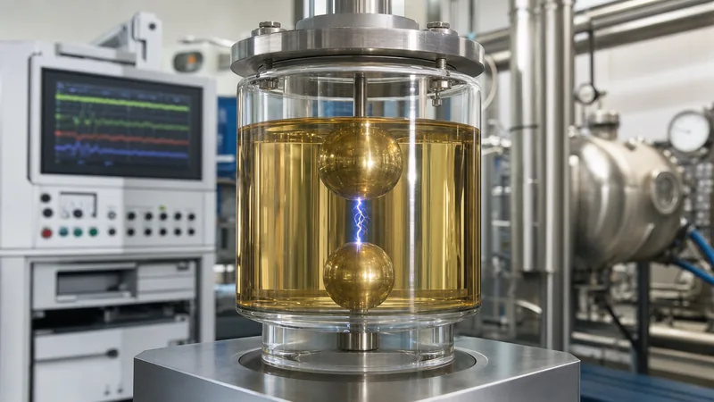
Dielectric breakdown voltage testing assesses the instantaneous electrical stress an insulating liquid can withstand between two submerged electrodes before a destructive arc occurs. Field engineers and factory testing technicians utilize two distinct electrode geometries and stirring configurations depending on the governing standard.
IEC 60156 mandates two brass, copper, or bronze electrodes shaped as spherical caps (spherical radius of 25 mm) or spheres (12.5 mm to 13.0 mm diameter) aligned on a horizontal axis with an exact 2.5 mm ± 0.05 mm separation gap. In contrast, ASTM D1816 prescribes spherically capped VDE electrodes with a polished surface, tested with continuous fluid motor agitation to maintain particulate suspension. Because ASTM D1816 stirs the fluid, it is substantially more sensitive to trace moisture droplets and microscopic cellulose fibres than older ASTM D877 flat-disk configurations. Factory acceptance criteria outlined in our power transformer testing documentation require vacuum treatment before final dielectric withstand checks.
The test sequence follows a strict laboratory routine:
- Clean the test cell thoroughly using petroleum spirit, rinse with filtered test oil, and verify electrode alignment using a precision go/no-go gauge.
- Pour the fluid sample slowly down the inside wall of the test cell to prevent the entrainment of air bubbles, leaving at least 15 mm of oil above the electrodes.
- Allow the sample to stand undisturbed for 5 minutes (under IEC 60156) to ensure that microscopic dissolved bubbles have fully escaped into the headspace.
- Apply an alternating test voltage at power frequency (45 Hz to 65 Hz) starting from zero, ramping steadily at a uniform rate of 2.0 kV/s ± 0.2 kV/s until breakdown occurs.
- Record the arc breakdown voltage instantly as the trip circuit interrupts the primary circuit within 10 milliseconds.
- Repeat the breakdown sequence six consecutive times on the same cell filling, maintaining a 2-minute pause between breakdowns, and calculate the arithmetic mean of the six readings.
Worked Calculation: Moisture Saturation and Breakdown Derating
A critical engineering calculation for transformer asset management is determining the relative moisture saturation percentage (RS%) of dielectric insulating oil at a specific winding temperature, because relative saturation, rather than absolute parts per million (ppm), governs breakdown voltage loss.
The water saturation solubility limit of uninhibited mineral oil dielectric fluid as a function of absolute temperature is defined by the Arrhenius relationship:
log₁₀(S) = A - (B / T)
Where S is water saturation solubility in ppm, T is the absolute oil temperature in Kelvin (K = °C + 273.15), and typical constants for standard mineral oil are A = 7.0895 and B = 1567 K.
Consider an operational 40 MVA transformer filled with 22,000 litres of mineral oil. A Karl Fischer titration sample taken at a bulk top-oil operating temperature of 60°C reveals an absolute moisture concentration of 24 ppm. What is the relative saturation, and what happens to the dielectric withstand margin if the unit trips and cools down to an ambient temperature of 15°C without changing total moisture mass?
Step 1: Calculate saturation limit at 60°C (333.15 K):
log₁₀(S₆₀) = 7.0895 - (1567 / 333.15) = 7.0895 - 4.7036 = 2.3859
S₆₀ = 10^(2.3859) = 243.2 ppm.
Relative Saturation at 60°C: RS = (24 ppm / 243.2 ppm) × 100 = 9.87%.
At below 15% relative saturation, the oil retains excellent dielectric withstand strength (>65 kV).
Step 2: Calculate saturation limit after shutdown at 15°C (288.15 K):
log₁₀(S₁₅) = 7.0895 - (1567 / 288.15) = 7.0895 - 5.4381 = 1.6514
S₁₅ = 10^(1.6514) = 44.8 ppm.
Assuming moisture migration back into the kraft paper has not yet occurred (which requires several weeks to reach equilibrium), the bulk oil water content remains roughly 24 ppm.
Relative Saturation at 15°C: RS = (24 ppm / 44.8 ppm) × 100 = 53.57%.
Result and Impact: As relative saturation increases past 40% to 50%, free water begins to emulsify with microscopic suspended fibres. Empirical curves in IEEE C57.106 show that at 53.6% relative saturation, the dielectric breakdown voltage drops from 70 kV down to approximately 28 kV—a 60% loss of insulation capacity. Re-energising the transformer under cold conditions without dynamic thermal pre-heating creates an acute flashover risk across terminal leads.
Degradation Mechanisms: Oxidation, Dissolved Gases, and Acidity
Degradation of mineral oil dielectric occurs through combined thermal oxidation, localized electrical discharges, and thermal decomposition of adjacent cellulose. Understanding fluid degradation pathways allows plant engineers to implement timely preventative intervention as detailed in our transformer maintenance engineering guide.
Atmospheric oxygen entering through conservator breather vents reacts with hydrocarbon chains at elevated temperatures. Hydroperoxides form first, followed by organic alcohols, aldehydes, ketones, and carboxylic acids. Carboxylic acids attack the metallic copper of winding conductors and structural steel, forming heavy metal soaps that polymerise into dark, sticky sludge. As sludge coats radiator panels, it increases thermal impedance, driving higher internal winding temperatures that accelerate the aging loop.
Simultaneously, internal electrical and thermal stresses decompose the hydrocarbon molecules into dissolved combustible gases:
- Hydrogen (H₂) and Methane (CH₄): Generated by partial discharges (corona) of low energy density across insulation voids.
- Acetylene (C₂H₂): Formed only at temperatures exceeding 700°C; its presence is a definitive indicator of high-energy arcing between winding turns or core laminations.
- Ethylene (C₂H₄): Produced under severe thermal overheating of the fluid (typically between 300°C and 700°C).
- Carbon Monoxide (CO) and Carbon Dioxide (CO₂): By-products of solid kraft paper pyrolysis, reflecting structural degradation of the primary dielectric barrier.
When the neutralisation number exceeds 0.15 mg KOH/g or the interfacial tension drops below 22 mN/m, plant operators must schedule vacuum dehydration, degasification, and reclamation through activated alumina or fuller's earth columns to prevent irreversible damage to internal solid insulation.
On-Site Sampling and Acceptance Checklist for EPC Contractors
Engineering, procurement, and construction (EPC) contractors must verify that dielectric insulating oil complies with strict purity standards before commissioning medium- and high-voltage substations. Improper sampling practices introduce ambient moisture, false particle counts, and invalid laboratory results.
The following checklist must be enforced during site delivery, oil filling, and pre-commissioning acceptance testing:
- Vessel Inspection: Confirm the transport tanker or steel drum features intact factory tamper-evident seals. Verify drum interiors are lined with epoxy lacquer to prevent direct iron-catalysed oil oxidation.
- Sampling Port Purge: Prior to drawing oil into glass sampling syringes or amber bottles (per IEC 60475), drain at least 4 to 8 litres of oil through the bottom drain valve into a waste vessel to flush stagnant particulates and moisture trapped in the valve dead-leg.
- Atmospheric Conditions: Never extract oil samples for breakdown voltage or Karl Fischer titration during precipitation or when ambient relative humidity exceeds 75%.
- Breakdown Voltage Baseline: Verify field-tested breakdown voltage meets or exceeds 60 kV for apparatus rated up to 69 kV, and 70 kV for apparatus rated at 115 kV or higher (IEC 60156 / ASTM D1816 2.0 mm).
- Water Content Verification: Ensure Karl Fischer moisture titration indicates less than 15 ppm for newly processed oil installed in high-voltage equipment prior to initial energisation.
- Dissolved Gas Baseline (DGA): Extract a baseline dissolved gas sample inside a gas-tight glass syringe within 24 hours of energisation to establish the project reference benchmark for future Duval triangle diagnostic evaluations.
Next steps: specifying and sourcing
When preparing technical bid evaluations or issuing a formal request for quotation (RFQ), clear procurement specifications for dielectric fluids protect system reliability. For new installations, EPC engineers must specify whether oil should be supplied in drums or pre-filled under positive nitrogen pressure. Explore our factory-tested range of power transformers and complete oil-immersed distribution units engineered to IEC, IEEE, and GB standards. To discuss specific dielectric withstand specifications, factory testing documentation, or custom cooling designs, submit your project schedule to our engineering department through our contact portal or request a rapid proposal via our direct quotation page.
Frequently asked questions
What is the primary function of dielectric insulating oil?
Dielectric insulating oil acts as an electrical insulator and convective cooling medium inside liquid-filled transformers. It suppresses electrical arcs, eliminates partial discharges across internal gaps, and transfers heat generated by winding and core losses to the tank walls and external cooling radiators.
What is the minimum acceptable breakdown voltage for transformer oil?
New untreated mineral oil dielectric fluid must achieve a minimum breakdown voltage of 30 kV under IEC 60156 (2.5 mm gap). Following factory vacuum dehydration and degasification, oil in newly filled high-voltage transformers must test at or above 70 kV before energisation.
What is the difference between inhibited and uninhibited dielectric oil?
Uninhibited oil contains no synthetic antioxidant additives, relying entirely on natural sulphur compounds for oxidation resistance. Inhibited oil contains synthetic phenolic oxidation inhibitors, typically 2,6-ditertiary-butyl para-cresol (DBPC) or 2,6-ditertiary-butyl phenol (DBP) up to 0.4% by weight, providing extended operational life under high thermal stress.
How does moisture affect dielectric insulating oil?
Dissolved and suspended moisture dramatically decreases the dielectric withstand strength of the oil. When relative water saturation exceeds 40%, breakdown voltage can plummet by more than 50%, while concurrently accelerating the hydrolytic degradation and mechanical embrittlement of the transformer's solid paper insulation.
When should transformer insulating oil be reclaimed or replaced?
Oil should be reclaimed or replaced when the neutralisation acid number exceeds 0.15 to 0.20 mg KOH/g, interfacial tension falls below 20 to 22 mN/m, or the dielectric breakdown voltage remains below 40 kV despite standard dehydration filtering.
Can ester-based fluids be mixed with mineral oil dielectric fluid?
While synthetic and natural ester fluids are miscible with mineral oil dielectric fluid in small amounts, intentional mixing is not recommended. Residual mineral oil in an ester-filled tank reduces the fire point below the 300°C K-class safety threshold defined by IEC 61039 and IEEE C57.147.
Tags: dielectric insulating oil mineral oil dielectric fluid mineral oil dielectric transformer testing substation engineering


