Key takeaways
- An industrial transformer steps medium-voltage grid distribution levels (typically 4.16 kV to 34.5 kV) down to plant utilization voltages between 208 V and 690 V.
- Industrial installations demand either dry-type cast resin units for indoor fire safety or mineral/ester oil-immersed transformers for outdoor heavy duty and high overload capacity.
- Impedance percentage (%Z) strictly determines downstream fault levels, with typical industrial ratings specified between 4.5% and 7.5% in compliance with IEC 60076 and IEEE C57.12.00.
- Evaluation of no-load (core) and load (winding) losses using Total Cost of Ownership (TCO) formulas significantly alters the lifetime economic comparison between standard and high-efficiency units.
- Rigorous Factory Acceptance Testing (FAT), including impulse tests and temperature rise verifications, is vital to mitigate premature dielectric breakdown in arduous factory environments.
Quick answer: An industrial transformer is a heavy-duty electrical machine engineered to step down utility transmission or distribution voltages (such as 11 kV, 22 kV, or 33 kV) to industrial working voltages (such as 400 V, 480 V, or 690 V) to power manufacturing equipment, motors, and process plants. They are built to withstand severe operating duty, harmonic currents, continuous cycling, and harsh environmental contaminants.
In heavy industrial processing, manufacturing plants, chemical refineries, and mining infrastructure, electrical continuity dictates plant profitability. Specifying an industrial power unit requires a balance between dielectric performance, short-circuit withstand withstandability, thermal rating, and integration with upstream switchgear. To make the correct purchasing decision, EPC contractors, project engineers, and facility managers must evaluate structural construction, cooling classifications, vector groups, and factory quality standards among leading electrical transformer manufacturers.
What is an industrial transformer and how does it work?
An industrial transformer is a stationary electromagnetic device that transfers alternating current electrical energy between circuits at the same frequency, adjusting voltage and current levels to match heavy mechanical and process loads. Working via electromagnetic induction according to Faraday’s Law, the incoming primary winding induces a magnetic flux in a laminated silicon-steel core, which couples to secondary windings to yield the required plant distribution voltage.
Unlike commercial or utility distribution units that endure steady, linear power consumption, an industrial unit routinely handles non-linear loads created by variable speed drives (VFDs), electric arc furnaces, robotic automation, and large induction motors. These demanding operating profiles generate significant third, fifth, and seventh harmonic currents, which amplify eddy current losses and induce thermal stress inside core-and-coil assemblies. To properly mitigate these phenomena, engineers refer to comprehensive resources on transformers internal components to evaluate core grain orientation, magnetic flux density, and multi-strand transposition conductors that lower parasitic skin-effect heating.
Industrial transformer types: oil-immersed vs dry-type
Industrial facilities predominantly rely on two fundamental transformer technologies: oil-immersed liquid-filled transformers and solid dry-type cast resin transformers. Choosing between them depends on installation location, environmental hazards, indoor fire ratings, and operational maintenance budgets.
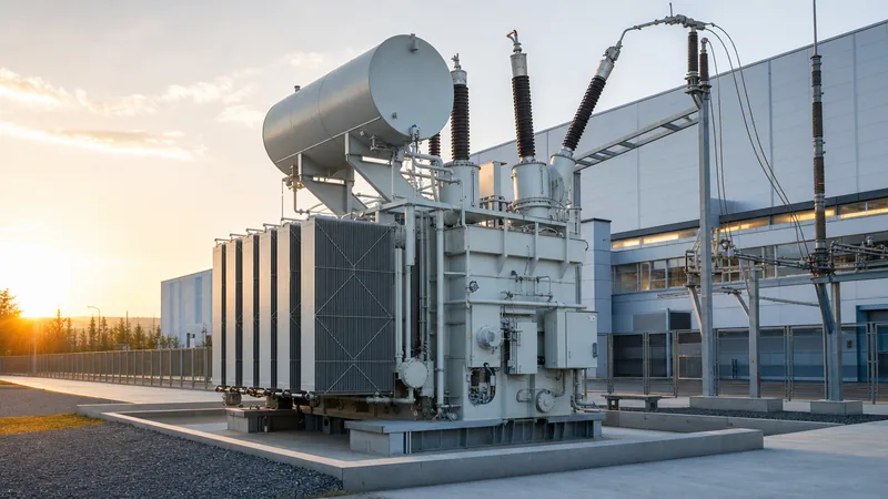
Oil-immersed transformers utilize high-grade dielectric fluid (uninhibited naphthenic mineral oil or synthetic/natural esters) to provide both internal electrical clearance and convective cooling. They deliver exceptional thermal performance, superior basic impulse insulation levels (BIL), and prolonged lifespans under outdoor continuous loading. Conversely, dry-type cast resin units enclose their high-voltage (HV) and low-voltage (LV) windings in vacuum-cast epoxy resin, eliminating flammable liquid handling, containment sumps, and fire deluge requirements inside sub-distribution rooms or high-density production zones. For a deep engineering comparison of these two cooling regimes, review our technical guide on oil-immersed vs dry-type transformers.
| Engineering Parameter | Dry-Type Cast Resin (VPI/CRT) | Oil-Immersed (Mineral / Synthetic Ester) |
|---|---|---|
| Applicable Standards | IEC 60076-11, IEEE C57.12.01 | IEC 60076-2, IEEE C57.12.00 |
| Voltage Class Capability | Up to 36 kV | Up to 110 kV+ |
| Cooling Designation | AN (Air Natural) / AF (Air Forced) | ONAN / ONAF / KNAN (Ester) |
| Basic Impulse Level (BIL) at 11 kV | 60 kV to 75 kV | 75 kV to 95 kV |
| Fire Risk Profile | Self-extinguishing (F1 rating) | Requires fire containment/catch pits |
| Overload Capacity (Short Duration) | Moderate (thermal inertia limited) | High (liquid bath thermal buffer) |
| Installation Location | Indoor switchrooms, basements | Outdoor yards, industrial substations |
Key technical specifications and sizing criteria
Sizing an industrial transformer requires computing continuous running loads, starting kVA demands of large squirrel-cage induction motors, power factor corrections, and system growth allowances. Undersizing a transformer triggers excessive winding temperature rises, degrading paper and resin insulation, whereas oversized units cause high capital costs and excessive continuous core energisation losses.
To establish the required apparent power in kilovolt-amperes (kVA), industrial engineers apply the fundamental 3-phase calculation:
S (kVA) = (V_LL × I_FLA × 1.732) / 1000
Where V_LL is line-to-line voltage in volts, and I_FLA is total full-load continuous current in amperes. When determining vector configurations, industrial standard practice typically incorporates delta-wye (Dyn11 or Dyn1) topologies to provide a stable, derived secondary neutral for single-phase 230 V loads while trapping third harmonic zero-sequence currents inside the delta primary winding. Comprehensive calculations for balanced configurations are outlined in our guide on delta wye transformer diagrams.
Impedance percentage (%Z) is an equally critical parameter. A standard industrial distribution unit between 1000 kVA and 2500 kVA typically features a %Z between 5.75% and 6.5%. Lower impedance improves voltage regulation during dynamic motor starting, but it concurrently raises available prospective symmetrical short-circuit currents on the secondary bus, requiring costlier, high-breaking-capacity switchgear downstream.
Evaluating transformer manufacturing and quality standards
High-reliability transformer manufacturing requires strict metallurgical controls, precision automated winding, low-tolerance core slitting, and controlled environmental assembly. Whether working with European, Asian, or american transformer manufacturers, industrial purchasers must insist on compliance with international standards such as IEC 60076 or IEEE C57.12 series.
During primary production, the core must be constructed from grain-oriented silicon electrical steel (CRGO), typically laser-scribed grades such as 23Q110 or 27Q120, cut with step-lap mitered joints to minimise magnetic reluctance and magnetising inrush current. Copper windings are standard for severe industrial service, wrapped in high-density thermally upgraded Nomex or Kraft paper. To ensure mechanical resilience against fault forces, clamping structures must withstand electromechanical stresses reaching several tonnes of force during an external bus fault. Before shipping from any professional transformer factory, units must undergo comprehensive testing aligned with our transformer factory acceptance testing checklist, validating insulation resistance, winding resistance, voltage ratio, phase displacement, load losses, and partial discharge levels.
What company makes transformers for heavy industrial plants?
Heavy industrial facilities source their equipment from specialised medium-voltage and high-voltage transformer manufacturing companies capable of engineering ruggedized units to specific project datasheets. Rather than purchasing standard utility off-the-shelf equipment, industrial buyers engage with bespoke distribution transformer suppliers, custom engineered switchgear assemblers, and certified power transformer manufacturers who understand arduous environmental constraints.
When procurement managers evaluate qualified transformer suppliers globally—including domestic suppliers and international manufacturing hubs—they assess production line automation, in-house dielectric testing labs, vacuum drying autoclave capacities, and independent test certifications from accreditation bodies like CE, UDEM, or EAC. Heavy duty facilities such as pulp mills, steel plants, data centres, and petrochemical complexes require engineering teams capable of integrating on-load tap changers (OLTC), sudden pressure relays, multi-point RTD temperature monitoring, and bespoke transformer housings into packaged substations.
Step-by-step procurement procedure for industrial transformers
A disciplined procurement procedure prevents costly design revisions, delayed factory delivery windows, and mismatched on-site connections. The following five steps guide engineering and procurement teams from initial specification to site integration:
- Define operating and site load profiles: Tabulate continuous load demand, anticipated motor starting currents, harmonic spectra (K-factor requirements), elevation above sea level, and ambient operating temperature ranges according to IEC 60076-1.
- Determine installation topology and enclosure rating: Select between outdoor mineral/ester liquid-filled pad-mounted configurations (weatherproof enclosure ratings) or indoor dry-type cast resin units (IP20 to IP31) based on facility fire safety protocols.
- Draft detailed technical tender datasheets: Explicitly state vector group (e.g., Dyn11), %Z impedance limits, winding material (copper vs aluminium), maximum permissible no-load/load losses (W), and required BIL withstand levels.
- Perform technical evaluation of manufacturer tenders: Compare loss capitalisation formulas using local electricity tariffs to determine the Total Cost of Ownership (TCO) across a 25-year operational lifecycle rather than deciding purely on initial capital purchase price.
- Witness Factory Acceptance Testing (FAT) and review documentation: Verify routine and type test certificates, dielectric breakdown test results of insulation fluid or cast epoxy, and seal approvals prior to dispatch and site offloading.
Next steps: specifying and sourcing
Specifying the optimal industrial transformer requires clear coordination between facility load profiles, medium-voltage network protections, and plant layout limits. To obtain an exact engineering design and competitive pricing proposal, prepare your site single-line diagram (SLD), preferred vector group, primary and secondary voltages, BIL constraints, and target delivery schedule. Explore our heavy-duty power transformer portfolio, custom oil-immersed transformers, and high-safety dry-type transformers designed for arduous industrial environments. For tailored tender proposals and comprehensive technical datasheets, request a quote at our quote page or directly reach our application engineering team via our contact page.
Frequently asked questions
what company makes transformers
Transformers are manufactured by specialized electrical equipment manufacturers ranging from global multinational engineering groups to dedicated regional power and distribution transformer factories. Industrial plants source custom units from certified transformer manufacturing companies capable of engineering units to IEC, IEEE, and ANSI standards.
What is the typical lifespan of an industrial transformer?
The typical lifespan of an industrial transformer ranges from 25 to 35 years under normal operating conditions. Longevity depends directly on operating temperature, effective dielectric insulation maintenance, loading within rated kVA limits, and protection against severe external short-circuit transients.
What K-factor should be specified for industrial transformers?
A K-factor between K-4 and K-13 is typically specified for standard industrial plants containing non-linear loads like variable speed drives. For heavy harmonic industrial environments with high concentrations of rectifiers, arc furnaces, or welding equipment, units rated at K-20 or K-30 are necessary to avoid overheating.
Why is Dyn11 the most common vector group in industrial facilities?
Dyn11 is the most common industrial vector group because its delta primary isolates third-harmonic zero-sequence currents while its wye secondary provides a stable neutral point for single-phase auxiliary loads. The 30-degree leading phase angle also simplifies parallel operation with standard utility networks.
How does ambient temperature affect industrial transformer rating?
Standard transformers are designed for an ambient temperature not exceeding 40°C with a 24-hour average of 30°C under IEC standards. If ambient temperatures exceed these design thresholds, the transformer must be derated by approximately 1% to 1.5% of its rated kVA per degree Celsius above the standard limit to prevent thermal breakdown of winding insulation.
Tags: industrial transformer power transformer manufacturers transformer manufacturing distribution transformer suppliers electrical transformer manufacturers


