Key takeaways
- Transformer infrared scanning requires a minimum continuous operating load of 40% (ideally above 60%) to generate detectable thermal gradients across high-resistance connections.
- Emissivity settings must be adjusted between painted transformer tanks (0.90 to 0.95) and bare, oxidised metal terminals or busbar connections (0.30 to 0.70) to prevent severe measurement errors.
- According to NETA MTS Table 100.18, a temperature difference between similar components under similar load exceeding 15 °C indicates a major deficiency requiring immediate repair.
- Thermal rise scales quadratically with current, meaning a moderate hot spot identified at partial load will experience an exponential temperature spike when operating near rated capacity.
- Systematic thermographic surveys capture not only external terminal loose joints but also internal anomalies such as blocked radiator tubes, eddy-current stray flux heating, and oil level discrepancies.
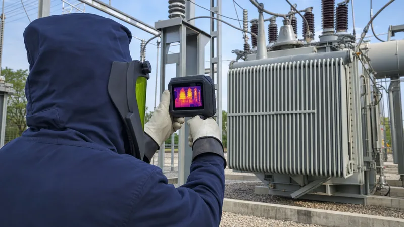
Quick answer: Transformer infrared scanning is an online, non-contact diagnostic method that detects abnormal thermal patterns caused by high-resistance electrical connections, blocked radiator tubes, defective bushings, and circulating core currents. Operating teams conduct thermography while the transformer is energised under load to prevent forced outages and catastrophic dielectric failure.
In industrial distribution systems and high-voltage substations, unexpected transformer failures lead to costly plant downtime and safety hazards. Thermal stress remains the leading accelerator of electrical insulation degradation, adhering to Arrhenius rate laws where every 6 °C to 8 °C temperature increase above thermal design limits halves transformer insulation lifespan. Because mechanical de-energisation for periodic contact resistance testing disrupts continuous production, non-intrusive condition monitoring is essential.
Routine transformer infrared scanning provides early warning of mechanical loosening, galvanic corrosion, oil circulation blockages, and harmonic overload. When deployed as part of an integrated predictive strategy alongside oil analysis and electrical testing, thermographic surveys allow facility managers to plan repairs during scheduled maintenance intervals rather than responding to emergency trips.
Core Principles of Transformer IR Scanning and Emissivity
Transformer IR scanning operates by measuring emitted long-wave infrared radiation (typically 7.5 to 14 μm wavelength) from external transformer surfaces and converting that radiometric flux into two-dimensional thermal images. Thermal energy emission depends heavily on surface emissivity (ε), which describes a material's efficiency in emitting thermal radiation relative to a theoretical blackbody radiator.
A critical source of error during electrical thermography is assuming a uniform emissivity across the entire apparatus. The painted mild steel or corrugated plate of a transformer main tank, conservator, and cooling radiators possesses a high emissivity, typically between 0.92 and 0.95. Bare copper lugs, galvanised structural hardware, and polished aluminium terminal clamps exhibit significantly lower emissivity values, often between 0.20 and 0.60. Pointing an infrared camera calibrated for ε = 0.95 at an unpainted copper bushing palm will result in an apparent temperature substantially lower than the actual component temperature, masking dangerous overheating.
Technicians must also account for solar loading, ambient cross-winds, and reflected apparent temperature. Wind speeds exceeding 4 m/s (15 km/h) induce convective surface cooling that masks underlying thermal anomalies on exterior radiators and terminal connections. When executing outdoor switchyard thermography, testing should be conducted under overcast skies, early in the morning, or at dusk to eliminate solar reflections from porcelain insulators and oil level sight glasses.
Critical Inspection Zones: Bushings, Tanks, and Cooling Banks
A comprehensive transformer IR inspection must evaluate distinct operational zones, each presenting unique thermal signatures and failure modes. Surveying the entire transformer assembly ensures both primary electrical current paths and secondary thermal dissipation systems function within specification.
Key inspection zones include:
- High-voltage and low-voltage bushings: Loose terminal studs, degraded internal draw-lead connections, and deteriorating capacitive layers produce localized hot spots. A thermal delta between phases indicates elevated contact resistance or dielectric losses. For deeper analysis of bushing failure modes, consult our transformer bushing engineering guide.
- Main tank walls and magnetic shielding: Localised hot spots on tank steel often point to stray flux heating caused by heavy harmonic loads, internal core ground faults, or failed electromagnetic shunts.
- Radiator banks and cooling fins: Operational cooling tubes should display a smooth, progressive temperature gradient, warmer at the top header pipe and cooler at the bottom return manifold. A cold radiator tube denotes an internal blockage, airlock, or closed isolation valve that prevents natural convective oil flow.
- On-load tap changer (OLTC) compartments: Under normal operation, the OLTC diverter compartment should run slightly cooler than the main tank. If the OLTC tank exhibits a higher surface temperature than the main tank, severe contact wear, arcing, or excessive circulating currents are present.
- Cable termination boxes and bus duct junctions: High-resistance crimps, improper torque on terminal pads, and unbalanced phase currents present acute thermal spikes at connection interfaces.
For broader preventative testing frameworks, review our guide on transformer maintenance.
Quantitative Temperature Severity Criteria
Thermographic findings are categorised using established temperature difference (ΔT) thresholds defined by international standards such as NETA MTS (Standard for Maintenance Testing Specifications) and NFPA 70B. These standards evaluate both component-to-component temperature deltas under identical loads and component-to-ambient temperature rises.
The following table outlines standard severity ratings and operational responses for electrical connections and transformer hardware:
| Severity Level | ΔT Over Similar Component (°C) | ΔT Over Ambient Air (°C) | Probable Root Cause | Recommended Corrective Action |
|---|---|---|---|---|
| Minor / Advisory | 1 to 3 | 1 to 10 | Minor surface oxidation, slight torque relaxation | Document anomaly; trend at next scheduled routine inspection |
| Intermediate | 4 to 15 | 11 to 20 | Moderate contact resistance, uneven bolt torque, light load imbalance | Schedule corrective maintenance at earliest planned outage |
| Serious | 16 to 30 | 21 to 40 | Severe contact degradation, heavy oxidation, internal draw-lead loosening | Repair as soon as possible; increase inspection frequency until corrected |
| Critical | > 30 | > 40 | Terminal melting risk, severe internal arcing, imminent connection separation | Immediate shutdown or selective load shedding to prevent failure |
These thresholds assume electrical components operate under significant load. If a terminal exhibits a 10 °C delta while operating under only 30% load, the condition is far more severe than the raw reading suggests due to exponential thermal scaling under full load.
Load Correction Calculation for Thermal Findings
Thermal dissipation across a resistive electrical joint is governed by Joule's Law ($P = I^2R$). Consequently, temperature rise above ambient does not scale linearly with load current, but rather exponentially according to load-correction relationships defined in IEEE C57 standards and thermography testing guidelines.
When an engineer observes a hot spot during low-load operation, the projected temperature rise at rated load is calculated using the following formula:
$$\Delta T_{rated} = \Delta T_{measured} \times \left( \frac{I_{rated}}{I_{measured}} \right)^{n}$$
Where $\Delta T_{measured}$ is the measured temperature rise over ambient, $I_{rated}$ is the rated nameplate current, $I_{measured}$ is the actual current during scanning, and $n$ is an empirical cooling exponent typically selected between 1.6 and 2.0 (with 1.8 to 2.0 standard for electrical connections dominated by natural convection).
Worked Engineering Example:
Consider a 2,500 kVA, 11 kV / 415 V oil-immersed distribution transformer operating under partial factory load during a plant survey:
- Rated secondary phase current ($I_{rated}$): 3,478 A
- Measured operating current during scan ($I_{measured}$): 1,400 A (approximately 40.2% load)
- Ambient air temperature ($T_{amb}$): 25 °C
- Measured temperature at low-voltage bushing terminal lug ($T_{meas}$): 65 °C
- Measured temperature rise ($\Delta T_{meas}$): $65 - 25 = 40$ °C
- Assumed exponent ($n$): 1.8
Calculate the projected temperature rise at full design capacity:
$$\Delta T_{rated} = 40 \times \left( \frac{3478}{1400} \right)^{1.8} = 40 \times (2.484)^{1.8} = 40 \times 5.109 = 204.4\text{ }^\circ\text{C}$$
Projected terminal operating temperature at full load:
$$T_{projected} = 25\text{ }^\circ\text{C} + 204.4\text{ }^\circ\text{C} = 229.4\text{ }^\circ\text{C}$$
While 65 °C appears manageable during the initial survey, the joint will reach 229.4 °C under rated load. This temperature far exceeds the 105 °C thermal limit of standard insulation and will result in catastrophic terminal lug failure or transformer fire. To understand winding limits under load, see our winding temperature transformer guide.
Step-by-Step Transformer IR Inspection Procedure
Executing an effective transformer ir inspection requires rigorous adherence to safety standards, equipment calibration, and methodical data recording. Electrical substations present arc-flash and electrocution hazards that require qualified personnel complying with NFPA 70E or local safety frameworks.
- Operational Load Verification: Ensure the transformer operates at a minimum of 40% steady-state electrical load for at least two hours prior to scanning. Thermographic surveys on unloaded or idling transformers will fail to reveal high-resistance connections.
- Environmental Assessment: Measure ambient temperature, relative humidity, and wind speed. Abort or shield outdoor testing if wind velocity exceeds 4 m/s or active precipitation is present.
- Camera Calibration and Parameter Input: Set camera focus, distance to target, ambient reflected temperature, and surface emissivity. When scanning painted radiators, apply ε = 0.94; for brass or bronze bushing palms, apply ε = 0.40 to 0.60.
- Initial Panoramic Scan: Capture overall thermal images of the transformer from all four quadrants to identify widespread anomalies, oil level lines on the main tank, and gross cooling bank imbalances.
- Targeted Component Analysis: Focus on high-voltage and low-voltage bushings, neutral ground connections, tap changer diverter tanks, bolted busbar splices, and tertiary windings. Record thermal profiles across all three phases simultaneously to establish comparative baselines.
- Radiator Bank Verification: Systematically scan radiator headers from top to bottom. Confirm that each radiator tube exhibits equivalent oil flow by comparing horizontal line profiles across radiator fins.
- Documentation and Corrective Flagging: Record peak hot spot temperature, component reference, current load (A and % rated), ambient conditions, and visual spectrum baseline photographs for every identified anomaly.
For factory-based baseline evaluation protocols, refer to our technical overview of power transformer testing.
Common Thermal Anomalies and Root Cause Analysis
Interpreting thermal signatures requires an understanding of both internal electromagnetic design and mechanical assembly practices. Different failure modes produce distinct thermal patterns across the transformer exterior.
Typical anomalies encountered during field scanning include:
- Point hot spots on terminal palms: A concentrated hot spot isolated to a single bolted interface signifies insufficient contact torque, thread galling, or interfacial galvanic corrosion between copper and aluminium components.
- Internal bushing draw-lead overheating: A temperature gradient that peaks high on the porcelain or composite insulator skirt rather than the external clamp indicates an internal fault, such as a loose draw-lead connection or moisture-induced dielectric breakdown in oil-impregnated paper (OIP) bushings.
- Thermal stratification failure in radiators: When an entire radiator panel remains cold while adjacent banks run warm, the failure stems from a closed radiator butterfly valve, internal sludge accumulation, or an air vapor lock preventing thermocline circulation.
- Abnormal conservator tank oil level: Infrared cameras clearly reveal the liquid-vapour interface inside the conservator tank due to the disparate thermal capacities of transformer oil and nitrogen or air. An oil level line below the minimum gauge indicator mandates immediate oil replenishment.
- Localised tank wall heating: Irregular thermal patches on structural steel tank walls often correlate with magnetic core ground failures, where double grounds create circulating loops that induce severe eddy currents in structural steel framing.
Next steps: specifying and sourcing
When specifying new equipment or preparing an engineering procurement package, incorporating infrared-friendly features significantly reduces long-term maintenance costs. Specifying integrated infrared inspection windows on cable termination boxes, clear line-of-sight bushing arrangements, and durable non-reflective external coatings ensures reliable online thermal scanning throughout the transformer lifecycle.
Our engineering team designs and manufactures utility-grade power transformers, industrial oil-immersed distribution transformers, and high-efficiency dry-type transformers engineered to international standards (IEC 60076, IEEE C57.12). For project engineering evaluations, technical compliance reviews, or quotation requests, visit our transformer quotation page or contact our technical sales group directly.
Frequently asked questions
What is the minimum load required for transformer infrared scanning?
A minimum electrical load of 40% of rated capacity is recommended, with 60% or higher preferred. Because thermal dissipation across a resistive joint scales with the square of the current, inspections conducted at low load may fail to reveal significant contact defects.
How often should transformer infrared scanning be performed?
Critical substation and industrial power transformers should undergo infrared scanning at least once every six to twelve months in accordance with NFPA 70B. High-load industrial transformers or equipment operating in severe harmonic environments should be scanned quarterly.
Can infrared scanning detect internal transformer faults?
Infrared scanning detects specific internal faults that transfer heat to the exterior, such as blocked cooling circuits, defective core ground loops, abnormal oil levels, and failing internal bushing connections. However, it cannot replace dissolved gas analysis for detecting deep winding insulation faults.
Why is emissivity correction critical during transformer IR inspection?
Emissivity dictates how efficiently a surface radiates thermal energy. Painted tank steel has a high emissivity (0.90 to 0.95), whereas bare copper or aluminium terminals have low emissivity (0.30 to 0.60); failing to correct the camera setting causes unpainted metal hot spots to appear deceptively cool.
What wind speed threshold invalidates an outdoor transformer IR scan?
Sustained wind speeds exceeding 4 m/s (approximately 15 km/h) invalidate outdoor thermographic inspections. Strong cross-winds induce rapid convective surface cooling, which artificially suppresses surface temperatures and conceals hazardous internal or contact hot spots.
Tags: transformer infrared scanning transformer ir scanning transformer ir inspection condition monitoring substation maintenance


