Key takeaways
- High-voltage source cables connect strictly to primary terminals marked H1, H2, and H3, while stepped-down loads connect to secondary terminals X1, X2, X3, and neutral X0.
- Correct system earthing requires bonding the transformer core, enclosure, and secondary neutral point (X0) to an earth electrode per IEC 60364 or NEC Article 250.
- Prior to energisation, insulation resistance tests between windings and from windings to earth must exceed 100 megaohms using a 1000V or 2500V DC insulation tester.
- Three-phase delta-wye (such as Dyn11) configurations isolate primary triplen harmonics while providing a stable neutral for unbalanced secondary phase-to-neutral loads.
- Overcurrent protective devices on the primary winding must account for magnetising inrush current, typically reaching 8 to 12 times the rated full-load current for several cycles.
Quick answer: To connect a step down transformer, terminate the higher-voltage supply conductors onto primary bushings H1, H2, and H3 (or H1 and H2 for single-phase), and attach the load distribution conductors to secondary bushings X1, X2, X3, and neutral terminal X0, ensuring the tank and neutral are bonded to earth before energisation.
Step-down transformers serve as foundational nodes in industrial distribution networks, stepping intermediate distribution voltages such as 11 kV, 13.8 kV, or 480 V down to usable utilisation voltages such as 415 V, 208 V, or 120 V. Improper connection practices compromise winding insulation, trigger severe phase mismatches, and present catastrophic arc-flash hazards. Whether you are installing a cast-resin dry-type unit in an electrical room or an outdoor liquid-filled unit, understanding the physics, connection geometry, and safety regulations governing these assets is paramount. For broader utility context, review our comprehensive Transmission Transformer Guide: Grid Engineering & Specs.
Terminal Markings and Polarity: How to Wire a Step Down Transformer
Standard transformer terminals are designated by alphanumeric characters where primary high-voltage terminals use the letter 'H' and secondary low-voltage terminals use 'X'.
According to standard IEC 60076-1 and IEEE C57.12.70 conventions, primary terminals are labelled H1, H2, and H3 for three-phase systems, or simply H1 and H2 for single-phase systems. The secondary, stepped-down windings are labelled X1, X2, X3, and X0, where X0 represents the star (wye) neutral connection point. Understanding winding polarity is critical whenever transformers are paralleled or integrated into metering systems. Polarity indicates the instantaneous relative direction of induced voltage between the primary and secondary terminals at any given moment.
In subtractive polarity transformers—standard on most three-phase units and single-phase units rated above 200 kVA or above 8.66 kV—terminal H1 is physically adjacent to terminal X1. Applying an instantaneous positive voltage wave to H1 results in an in-phase positive voltage at X1. When mastering how to wire a step down transformer, matching line phases (Phase A to H1, Phase B to H2, Phase C to H3) ensures the internal magnetic fluxes align with the manufacturer design. Incorrect terminal sequencing can invert phase angles, induce reverse rotation on industrial induction motors, and cause circulating currents if interconnected with an adjacent substation feeder. For foundational concepts on voltage conversion and ratios, consult our guide on Step Down Power Transformer: Sizing, Specs & Price Guide.
Pre-Installation Safety and Field Verification Checks
Pre-installation safety requires establishing an electrically safe work condition through verified isolation, lockout-tagout (LOTO), and visual earth application.
Before touching terminal pads or unwrapping cable terminations, verify zero energy state using an intrinsically safe, calibrated medium-voltage proximity detector or contact voltmeter. Once mechanical mounting on the plinth or pad is secured, technicians must execute field verification tests to ensure the unit did not suffer internal shock during transport. A primary prerequisite is the insulation resistance (IR) test conducted with a calibrated megohmmeter.
Apply test voltages according to winding voltage classes: typically 1000 V to 2500 V DC for medium-voltage windings and 500 V to 1000 V DC for low-voltage windings. Minimum acceptable insulation values after one minute should conform to standard IEEE 43 and NETA ATS recommendations, generally exceeding 100 MΩ at 20°C. Compare measured values against factory test reports for winding resistance, turns ratio (TTR), and core ground integrity. For step-by-step testing methodologies across factory and field environments, refer to our detailed manual on How to Test a Transformer: Field and Factory Testing Guide.
Step-by-Step Procedure: How to Connect Step Down Transformer Cables
Terminating power cables onto a step-down transformer requires methodical torque control, phased identification, and stress-cone management on shielded conductors.
- De-energise, lock out, and earth: Confirm isolation on upstream circuit breakers or switch-disconnectors. Apply trailing earths to all incoming medium-voltage conductors to eliminate residual capacitive charges.
- Prepare the cable ends: Strip medium-voltage or low-voltage cables using designated peeling tools to avoid scoring the conductor strands. On shielded MV cables, install certified stress-relief termination kits to dissipate electrical stress concentrations at the insulation screen boundary.
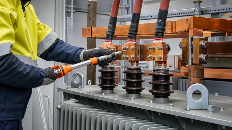
- Connect the primary high-voltage cables: Bolt the incoming phase conductors to primary terminals H1, H2, and H3 using high-tensile stainless steel or silicon bronze fasteners. Always install flat washers and Belleville conical spring washers to maintain constant clamp force across thermal expansion cycles. Torque bolts precisely to the manufacturer specification (typically 40 Nm to 55 Nm for M12 copper hardware).
- Connect the secondary low-voltage busbars or cables: Secure output phase conductors to terminals X1, X2, and X3. On delta-wye transformers delivering three-phase four-wire distribution, attach the system neutral conductor firmly to bushing X0.
- Bond the neutral and equipment earth: Run a copper equipment grounding conductor (EGC) and a grounding electrode conductor (GEC) from the internal transformer earthing bus to the main substation earth grid. Install a removable bonding jumper between X0 and the enclosure ground bus if the transformer constitutes a separately derived system per NEC Article 250.30 or local utility bylaws.
- Install protective covers and barrier partitions: Reinstall all phase barriers, transparent terminal shrouds, and enclosure access panels. Verify that minimum electrical clearance distances in air (e.g., minimum 150 mm clearance for 11 kV terminations per IEC 60076-3) are maintained across all live conductors.
Earthing, Grounding, and Vector Group Alignment
Earthing arrangements dictate fault clearing performance, transient overvoltage suppression, and personnel safety during line-to-ground insulation breakdowns.
In a standard industrial Dyn11 step-down transformer, the high-voltage winding is connected in Delta (D), the secondary winding is connected in Star/Wye (y) with an accessible neutral (n), and the secondary phase voltage lags the primary phase voltage by 30 degrees (represented by the clock number 11). The delta primary traps zero-sequence harmonic currents—specifically third, ninth, and fifteenth harmonics produced by non-linear rectifiers and variable speed drives—preventing them from propagating upstream into the transmission grid.
Solid grounding of secondary neutral X0 establishes a low-impedance path for ground-fault current, enabling upstream protection relays and molded-case circuit breakers (MCCBs) to trip instantaneously during phase-to-earth faults. If the secondary system operates as an ungrounded or high-resistance grounded (HRG) network to preserve process continuity, connect a neutral grounding resistor (NGR) rated for continuous or 10-second duty between X0 and the earth mat. Failure to firmly earth the transformer tank chassis can allow stray capacitive voltages to elevate metal enclosure surfaces to dangerous potentials. Comprehensive protective scheme design is outlined in our pillar guide on Transformer Protection: The Complete Substation Engineering Guide.
Cable Sizing, Protection Ratings, and Electrical Characteristics
Calculating correct cable cross-sections and protective breaker thresholds requires accounting for continuous load currents, fault levels, and severe magnetising inrush dynamics.
Use the standard three-phase power formula to determine continuous rated currents on both windings:
I = S / (√3 × V)
where S is transformer apparent power in kVA, V is line-to-line voltage in kilovolts, and I is full-load current in amperes. Because the primary side sees a high inrush current reaching 8 to 12 times rated full-load current for 100 milliseconds upon core energisation, primary protective fuses or circuit breakers must feature an inverse-time characteristic or electronic short-time delay (ANSI device 51) to avoid nuisance tripping. The table below details representative electrical values for standard step-down transformers across common industrial transformation ratings.
| Capacity (kVA) | Primary Voltage (kV) | Secondary Voltage (V) | Primary Current (A) | Secondary Current (A) | Nominal Impedance (%Z) |
|---|---|---|---|---|---|
| 500 | 11.0 | 415 | 26.2 | 695.6 | 4.50% |
| 1000 | 11.0 | 415 | 52.5 | 1391.2 | 5.00% |
| 1500 | 13.8 | 480 | 62.8 | 1804.2 | 5.75% |
| 2000 | 13.8 | 480 | 83.7 | 2405.6 | 6.00% |
| 2500 | 33.0 | 415 | 43.7 | 3478.0 | 6.50% |
Secondary conductor cross-sections must be sized not only for continuous full-load ampacity under site ambient temperature deratings, but also to withstand thermal and mechanical stresses during a prospective secondary short circuit. Short-circuit prospective current is directly governed by nameplate percentage impedance (%Z):
I_sc = I_rated / (%Z / 100)
For instance, a 1000 kVA transformer with 5.0% impedance generates an available secondary fault current of approximately 27.8 kA, demanding appropriately rated switchgear busbars and breaking capacities.
Energisation, Testing, and Commissioning Sequence
Commissioning follows a structured sequence comprising visual checks, cold electrical testing, no-load soak testing, and balanced load release.
Prior to turning the primary protection switch to closed, check oil levels in conservator tanks or inspect dry-type cast resin coils for surface cleanliness and moisture contamination. Verify that tap changer settings—whether an off-circuit tap selector or an on-load tap changer (OLTC)—match actual grid supply voltage to avoid sustained secondary overvoltage or undervoltage conditions.
Perform the initial energisation with all secondary downstream load breakers open (no-load state). When the upstream breaker closes, listen for the characteristic magnetic hum of core lamination magnetostriction. Abnormal rattling, sharp cracking sounds, or persistent chattering indicates loose laminations, phase imbalance, or loose terminal hardware. Measure secondary line-to-line and line-to-neutral voltages using a calibrated digital multimeter across all phase-to-phase and phase-to-neutral terminals. Line-to-line measurements must match design outputs within ±2.5%, and phase rotation must be verified using a phase-sequence rotation meter before closing loads onto industrial three-phase machinery.
Next steps: specifying and sourcing
Specifying a transformer tailored to your site parameters ensures seamless installation and long operating lifetimes. When requesting equipment quotations or technical proposals, prepare your site-specific parameters: primary and secondary voltage ratings, system frequency (50 Hz or 60 Hz), required kVA rating, winding configuration and vector group, enclosure protection index (IP rating), and environmental ambient constraints. For indoor industrial distribution plants, review high-efficiency dry-type transformer solutions, or explore robust outdoor liquid units via our oil-immersed transformer range. Our engineering team is ready to evaluate your single-line diagrams, review short-circuit requirements, and manufacture custom distribution units to IEC and IEEE standards. Submit your technical project specifications directly to our application specialists through our transformer quote page.
Frequently asked questions
how to connect step down transformer
To connect a step down transformer, bring the higher-voltage incoming supply lines onto primary terminals marked H1, H2, and H3, and wire the output load cables to secondary terminals X1, X2, and X3. On delta-wye configurations, connect the system distribution neutral to terminal X0, and secure all equipment ground points to the earth grid.
how to wire a step down transformer
To wire a step down transformer, first verify complete circuit isolation and earth all conductors. Secure supply cables to primary bushings H1 and H2 (or H1, H2, H3 for three-phase), terminate secondary cables to X1 and X2 (or X1, X2, X3, and X0), torque bolts to specification, and bond the tank chassis to earth.
Can you wire a step down transformer in reverse to step up voltage?
Yes, many standard distribution transformers are bidirectional and can function in reverse, but doing so alters internal voltage regulation and inrush characteristics. The original secondary winding becomes the primary, meaning higher inrush currents can trip upstream breakers, and turns-ratio compensation for internal impedance will cause secondary output voltage to dip lower than rated.
What size earth cable is required for a step-down transformer?
Earth conductor size is determined by prospective ground fault current and local electrical codes such as NEC Table 250.66 or IEC 60364-5-54. As a rule of thumb, copper earthing conductors must be sized based on the cross-sectional area of the largest ungrounded phase conductor, typically requiring minimum sizes between 16 mm² and 95 mm² for industrial distribution transformers.
Why is the secondary neutral terminal X0 bonded to ground?
Terminal X0 is bonded to ground to stabilise phase-to-neutral voltages against floating potentials and provide an immediate, low-impedance return path for earth-fault currents. Without neutral grounding, a single phase-to-earth fault would stress winding insulation on unfaulted phases with full line-to-line voltage, risking insulation failure and personnel shock.
Tags: step down transformer transformer wiring electrical installation substation engineering three phase transformer


