Key takeaways
- Inside a corner delta transformer, three secondary phase windings are connected in a closed delta loop with one phase terminal (conventionally Phase B / X2) solidly bonded to the ground bus.
- A corner grounded delta 240V system produces 240 V line-to-line, but reads 240 V from Phase A to earth, 240 V from Phase C to earth, and 0 V from Phase B to earth.
- Straight-rated circuit breakers (e.g., 240 V or 480 V) are strictly required because slash-rated breakers (such as 120/240 V or 480Y/277 V) cannot handle full phase-to-phase potential to earth.
- Unlike an ungrounded delta system, a corner-grounded arrangement stabilises phase-to-ground potentials against transient overvoltages and ensures immediate trip on first line-to-ground faults.
- Under NEC Article 240.22, overcurrent devices must not be installed in the grounded phase conductor unless the device opens all ungrounded circuit conductors simultaneously.
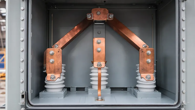
Quick answer: Looking inside a corner delta transformer reveals a standard three-phase delta-connected secondary winding where one of the phase corners—typically the B-phase terminal (X2)—is solidly bonded to earth via an internal or enclosure grounding strap, providing a ground reference without a central neutral point.
In three-phase distribution, corner-grounded delta configurations (often termed an earthed-leg delta) remain prevalent across industrial facilities, municipal pump stations, and legacy installations. Understanding what takes place inside a corner delta transformer is vital for plant engineers, switchgear specifiers, and electrical contractors facing unusual multimeter measurements, replacement requirements, or selective coordination challenges. While the electromagnetic assembly resembles any standard delta secondary, the intentional earthing of one line conductor alters fault current paths, instrument transformer hook-ups, and protective device sizing.
For broader context on three-phase terminal labelling and vector conventions, see our detailed guide on transformer wiring schematics and diagrams.
Inside a Corner Delta Transformer: Core and Winding Architecture
Inside a corner delta transformer, the physical active assembly consists of a laminated silicon-steel magnetic core and three independent phase coils wound for primary and secondary voltages. On the secondary side, the coil ends are linked in series—finish of phase 1 to start of phase 2, finish of phase 2 to start of phase 3, and finish of phase 3 to start of phase 1—creating a closed triangular winding mesh adhering to IEEE C57.12.00 standards.
The defining mechanical and electrical variation lies at the secondary bushings and the internal earth busbar:
- Absence of an X0 Bushing: Unlike a four-wire wye (star) secondary, there is no common neutral point. The tank head or cable box contains only three low-voltage terminals: X1, X2, and X3.
- The Corner Bonding Strap: A low-impedance copper link bonds one designated corner (standardised as X2 under NEMA and IEEE field conventions) directly to the transformer tank earth bus and the external grounding electrode conductor (GEC).
- Coil Insulation Class: The winding coils must feature full line-to-line dielectric insulation throughout the entire coil assembly. Because the ungrounded phases operate at full line voltage relative to the core steel and tank walls, graded insulation cannot be deployed.
Whether built as an oil-immersed transformer or a dry-type transformer, the internal active iron-core assembly does not differ electromagnetically from an ungrounded delta unit; the operational divergence is created entirely by the deliberate grounding of that single corner terminal.
Voltage Profiles and Vector Relationships: Corner Grounded Delta 240V
A corner grounded delta 240V system produces symmetrical phase-to-phase voltages alongside highly asymmetrical phase-to-ground voltages. When an electrician or commissioning engineer applies a calibrated voltmeter between terminals, the line-to-earth readings frequently cause confusion if the system design is unfamiliar.
Consider a balanced 240 V line-to-line system where Phase B is solidly grounded at the transformer terminal X2. The resulting electrical potentials to earth and between lines are shown below:
| Measurement Path | Nominal Potential | Phase Angle vs Phase A-B | Vector Derivation |
|---|---|---|---|
| Line A to Line B (X1 to X2) | 240 V | 0° | Full secondary winding potential |
| Line B to Line C (X2 to X3) | 240 V | 120° | Full secondary winding potential |
| Line C to Line A (X3 to X1) | 240 V | 240° | Full secondary winding potential |
| Line A to Earth (X1 to Ground) | 240 V | 0° | V_A - V_B (where V_B = 0 V reference) |
| Line B to Earth (X2 to Ground) | 0 V | — | Solid direct bond to earth grid |
| Line C to Earth (X3 to Ground) | 240 V | 120° | V_C - V_B (where V_B = 0 V reference) |
Because Phase B is fixed at zero volts earth potential, the two ungrounded lines (A and C) maintain a continuous 240 V stress with respect to ground. If you are verifying transformer installations during commissioning, consult our engineering guide on field and factory testing procedures to ensure test voltages do not overstress line-to-case test sets.
Corner Grounded Delta vs Ungrounded Delta vs Solidly Grounded Wye
Selecting a corner-grounded delta rather than an ungrounded delta or a four-wire wye configuration involves specific operational trade-offs regarding ground-fault detection, overvoltage control, and equipment costs. Many legacy textile, chemical, and heavy processing facilities installed delta systems solely to power three-wire motor loads without the added copper expense of running a fourth neutral conductor.
| System Parameter | Corner Grounded Delta (240 V) | Ungrounded Delta (240 V) | Solidly Grounded Wye (480Y/277 V or 208Y/120 V) |
|---|---|---|---|
| Phase-to-Earth Potential | Asymmetrical (0 V on grounded leg, full line-to-line on others) | Floating (theoretically balanced by cable capacitance) | Symmetrical (Line voltage divided by 1.732) |
| Single Line-to-Ground Fault | High fault current immediately; trips overcurrent device | Minimal capacitive fault current; system remains operating | High fault current immediately; trips overcurrent device |
| Transient Overvoltage Risk | Low; system reference is solidly tied to earth | High; arcing ground faults can induce severe overvoltages | Low; neutral establishes firm potential clamp |
| Neutral Conductor Required | No (3-wire distribution) | No (3-wire distribution) | Yes (4-wire distribution for dual voltage) |
| Lighting Load Capability | None direct; requires auxiliary 1-phase step-down unit | None direct; requires auxiliary 1-phase step-down unit | Excellent; direct line-to-neutral connection available |
| Breaker Voltage Rating Rule | Straight-rated breakers required (e.g., 240 V) | Straight-rated breakers required | Slash-rated breakers permitted (e.g., 120/240 V, 480Y/277 V) |
To understand overall industrial plant architecture and distribution strategies, see our article on industrial power system installation.
Protection, Breaker Sizing, and NEC Grounding Rules
Protective coordination on a corner-grounded delta secondary requires strict adherence to electrical codes, notably NFPA 70 (National Electrical Code / NEC) and IEC equivalent standards, due to the presence of an earthed phase conductor.
Key engineering mandates include:
- Circuit Breaker Voltage Rating: Standard slash-rated molded case circuit breakers (MCCBs)—such as 120/240 V or 480Y/277 V—are evaluated for an earthed neutral system where phase-to-ground voltage does not exceed the lower number. In a corner-grounded delta, the phase-to-ground voltage on ungrounded poles is the full line voltage (240 V or 480 V). Therefore, you must specify straight-rated protective devices (rated 240 V or 480 V). Installing slash-rated breakers on this topology violates NEC Article 240.85 and invites catastrophic dielectric breakdown during interruption.
- Overcurrent Protection on the Grounded Conductor: Under NEC Article 240.22, no overcurrent device (fuse or breaker pole) may be placed in series with a conductor that is intentionally grounded, unless the disconnect opens all conductors simultaneously. Consequently, design engineers use either two-pole breakers (switching only the ungrounded phases) or three-pole breakers that open all three poles simultaneously. Fuses must never be placed on the grounded Phase B conductor.
- Conductor Identification: NEC Article 250.119 dictates that the grounded phase conductor must be identified by white or grey outer finish or distinctive white marking at termination points, ensuring technicians do not confuse it with an ungrounded phase.
For detailed protective scheme calculations, refer to our comprehensive review of substation and transformer protection.
Step-by-Step Field Identification and Verification Procedure
Engineers encountering an unmarked transformer installation can safely identify a corner-grounded delta using systematic electrical and visual verification steps.
- Perform Visual Inspection and De-energised Isolation: Lock out and tag out (LOTO) the primary switchgear. Inspect inside the low-voltage terminal compartment. Look for a heavy copper bonding jumper connecting one terminal lug directly to the enclosure ground pad.
- Measure Insulation Resistance to Earth: Utilising a 1000 V insulation resistance tester (Megohmmeter), disconnect the system bonding jumper and measure from each secondary phase winding to ground. All three coils should demonstrate high insulation resistance (typically greater than 100 MΩ at 20 °C). Reconnect the factory bonding jumper securely.
- Energise and Measure Line-to-Line Voltages: With appropriate Personal Protective Equipment (PPE) rated for the available arc flash boundary, measure each phase-to-phase terminal pair with a calibrated digital multimeter. All three values must measure the nominal line-to-line potential within standard tolerance (e.g., 240 V ± 2%).
- Measure Line-to-Earth Voltages: Measure each terminal to the enclosure ground bus. If the system is a corner grounded delta 240V installation with grounded Phase B, X1-to-ground reads 240 V, X3-to-ground reads 240 V, and X2-to-ground reads 0 V.
- Check Phase Rotation: Connect an analogue or digital phase sequence indicator to confirm clockwise (A-B-C) or counter-clockwise rotation before energising directional motor loads.
Specifying a Replacement Delta Transformer: Engineering Checklist
When specifying a new unit to feed a legacy corner-grounded installation, the technical procurement specification must prevent standard wye assumptions from entering the design phase.
Use the following engineering schedule when preparing your Request for Quotation (RFQ) for factory engineering:
| Specification Parameter | Standard Factory Requirement | Engineering Rationale |
|---|---|---|
| Secondary Configuration | 3-Phase, 3-Wire Delta (e.g., 240 V or 480 V Delta) | Prevents manufacturer from winding an unneeded X0 neutral leg. |
| System Earthing Designation | Corner Grounded (Specify Phase B / X2 earthing) | Directs factory to install internal or external bonding link provisions. |
| Winding BIL Rating | Full line-to-line Basic Impulse Level across all legs | Ensures ungrounded legs have required dielectric clearance to core. |
| Transformer Enclosure | NEMA 3R / IP54 (Pad-mounted or Substation type) | Matches installation ambient for utility or industrial duty. |
| Low-Voltage Bushing Count | 3 LV bushings (X1, X2, X3) + 1 Tank Ground Pad | Eliminates unnecessary fourth bushing; saves terminal box space. |
| Impedance (%Z) | Standard per IEEE C57.12.00 (typically 4.5% to 5.75%) | Limits downstream short-circuit current during line-to-ground faults. |
Whether sourcing a medium-voltage step-down unit for a modern pad-mounted transformer installation or an engineered unit substation, making earthing requirements explicit avoids site rework during commissioning.
Next steps: specifying and sourcing
Configuring power transformers for non-standard grounding topologies requires experienced design validation, precise coil dielectric engineering, and factory testing that adheres strictly to IEC 60076 and IEEE C57 standards. If you are retrofitting a facility, replacing an aged substation transformer, or designing switchgear for a corner-grounded network, our engineering team can review your single-line diagram and generate custom coil calculations. Submit your technical schedule and kVA requirements through our transformer quote portal or contact our technical sales desk via our contact page to receive detailed design drawings and commercial proposals.
Frequently asked questions
Why would someone use a corner grounded delta transformer?
A corner-grounded delta provides a solid ground reference without the cost of a neutral conductor, stabilising phase voltages against transient surges while providing sufficient fault current to quickly trip overcurrent devices during ground faults on ungrounded phases.
What happens if a ground fault occurs on a corner grounded delta system?
A ground fault on either of the two ungrounded phases creates a direct phase-to-phase short circuit through the grounded corner, driving high fault current that causes protective breakers or fuses to trip instantaneously.
Can you get 120V from a corner grounded delta 240V transformer?
No, you cannot obtain 120 V directly from a corner grounded delta 240V system because there is no neutral conductor or centre tap. A separate single-phase dry-type control transformer must be installed to supply 120 V single-phase loads.
Which phase is typically grounded in a corner delta transformer?
Phase B (connected to the X2 bushing) is the conventional standard for grounding in North American practice under NEMA and IEEE guidelines, though grounding Phase A or Phase C is electrically identical if consistently documented.
Why are slash-rated circuit breakers prohibited on corner grounded systems?
Slash-rated breakers (such as 120/240 V or 480Y/277 V) are only tested for line-to-ground potentials equal to the lower voltage rating. In a corner-grounded delta, the ungrounded phases experience full line-to-line potential to earth, requiring straight-rated breakers.
Tags: corner delta transformer corner grounded delta 240v transformer wiring industrial grounding delta secondary


