Key takeaways
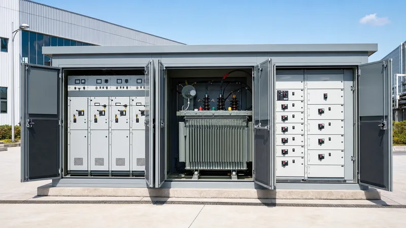
- A packaged transformer unit integrates medium-voltage switchgear, a step-down core-and-coil assembly, and low-voltage distribution into a single factory-tested enclosure.
- Evaluating transformer energy efficiency requires calculating both core losses and load losses under expected operating load profiles according to IEC 60076-1 clause 10.4.
- Impedance voltage (%Z) directly governs fault levels and voltage regulation, typically specified between 4.0% and 6.0% for distribution ratings up to 2,500 kVA.
- Selecting between radial and loop feed configurations dictates whether internal load-break switches and bay-o-net fusing or circuit breakers are required in the MV compartment.
- Factory acceptance testing must verify insulation resistance, winding resistance, voltage ratio, and temperature rise limits prior to site dispatch.
Quick answer: A transformer unit is an engineered power distribution assembly comprising a primary medium-voltage interface, a magnetic core-and-coil voltage step-down stage, and secondary low-voltage protection switchgear housed within a unified, weather-resistant enclosure. It provides safe, decentralised power transformation for industrial plants, renewable generation sites, and commercial facilities.
In decentralised distribution networks, engineers must balance spatial footprints, ingress protection, and thermal dissipation. The modern box-type or prefabricated transformer unit replaces traditional open-yard civil substations by integrating the transformer and protective switchgear into a compartmentalised steel or concrete housing. For a comprehensive system overview, consult our unit substation engineering guide to understand broader network topologies.
What Is a Transformer Unit in Box-Type Substations?
A transformer unit in a box-type substation functions as the central node linking the medium-voltage (MV) utility grid to low-voltage (LV) facility distribution boards. Rather than sourcing distinct switchgear panels, external cabling, and oil or dry transformers separately, engineers deploy a compact, factory-assembled package designed to comply with IEC 62271-202 standards for high-voltage/low-voltage prefabricated substations.
Internally, the structure features three galvanically and physically segregated compartments: the medium-voltage compartment, the transformer housing, and the low-voltage switchboard. The medium-voltage section typically houses a ring main unit (RMU) with vacuum circuit breakers or load-break switches insulated by gas or solid dielectric media. The transformer compartment contains either an oil-immersed core (mineral oil, synthetic ester, or natural ester) or a cast resin dry-type block. The low-voltage chamber houses air circuit breakers (ACBs) or moulded case circuit breakers (MCCBs), power factor correction capacitors, and revenue-grade metering equipment.
By enclosing the entire apparatus within a rated steel housing—often powder-coated to achieve C4 or C5 corrosion resistance classes under ISO 12944—the installation footprint shrinks by up to 70% compared to open-air yards, whilst dramatically improving touch-safe operator protection.
Transformer Energy Efficiency and Loss Calculations
Optimising transformer energy performance requires rigorous analysis of both no-load core losses and load-dependent copper losses across the expected operating lifecycle. Regulatory frameworks such as EU Ecodesign Directive (EN 50588-1 Tier 2) and IEEE C57.12.00 mandate stringent limits on dissipation to curtail wasted primary generation.
Total continuous power loss in a transformer is calculated using the following formula:
Ptotal = P0 + (m2 × Pk)
Where P0 is no-load loss in kilowatts (kW), Pk is load loss at rated current and reference temperature (75 °C for liquid-immersed, 120 °C for cast resin), and m is the loading factor (actual load divided by rated capacity). Consider a typical 1,000 kVA oil-immersed transformer unit running continuously at an average 65% load factor (m = 0.65). Typical Tier 2 performance yields P0 = 1.10 kW and Pk = 9.50 kW:
Ptotal = 1.10 + (0.652 × 9.50) = 1.10 + (0.4225 × 9.50) = 1.10 + 4.014 = 5.114 kW
To evaluate the annual cumulative transformer energy loss over 8,760 operating hours:
Energy Loss = 5.114 kW × 8,760 h = 44,798.6 kWh/year
Evaluating lifecycle capitalization of losses alongside initial procurement expenditure ensures capital budgets account for total operating costs over a 25- to 30-year design life. Detailed mathematical methods for choosing ratings can be found in our transformer sizing calculator guide.
Transformer Unit Configurations: Radial vs Loop Feed Architecture
Primary feeder arrangement determines whether a transformer unit is specified with radial or loop feed incoming switchgear. The selection governs site operational flexibility, fault isolation speeds, and cable trench design across the site.
A radial feed configuration supplies power via a single incoming MV cable circuit terminating directly on transformer bushings or via a single load-break disconnect switch. While cost-effective and straightforward to commission, any primary cable fault interrupts power to the entire unit until the physical run is repaired. Conversely, loop feed installations connect into a closed or open ring network via a two-position or four-position MV switch arrangement. If an upstream cable section fails, field operators can isolate the damaged segment and re-energise the unit via the alternate feeder arm in minutes.
When deciding between these two distribution layouts, explore our comparative engineering study on radial feed vs loop feed topologies to evaluate protection relay coordination and switching sequence risks.
Engineering Specifications and Sizing Checklist
Specifying a transformer unit demands precise technical coordination between electrical parameters, mechanical constraints, and environmental variables. The table below outlines standard electrical and mechanical baseline parameters per IEC 60076 and IEEE C57.12.00 specifications.
| Engineering Parameter | Standard Industrial Range | Governing Standard | Design Consideration |
|---|---|---|---|
| Rated Power (kVA) | 500 to 2,500 kVA | IEC 60076-1 / IEEE C57.12.00 | Continuous loading plus harmonic derating factor (K-factor) |
| Primary Voltage (kV) | 11 kV, 22 kV, 33 kV | IEC 60071-1 | Basic Impulse Insulation Level (BIL) matching grid utility class |
| Secondary Voltage (V) | 400/230 V, 480/277 V, 690 V | IEC 60038 | System earthing scheme (TN-S, TN-C-S, or IT) |
| Impedance (%Z) | 4.0% to 6.0% | IEC 60076-1 clause 5.4 | Limits short-circuit fault current and voltage drop on motor start |
| Cooling Class | ONAN, KNAN, AN, AF | IEC 60076-2 | Natural or forced cooling; synthetic fluid reduces fire clearance |
| Ingress Protection | IP23 (dry) to weatherproof ratings (oil) | IEC 60529 | Ventilation louvre baffles against driving rain and sand entry |
| Enclosure Material | 2.0 mm Galvanised / Aluzinc Steel | ISO 12944 | Corrosion protection against saline or petrochemical atmospheres |
Correct impedance selection (%Z) is particularly critical: a lower %Z minimises load-dependent voltage drop during the starting of large induction motors, but proportionally increases downstream fault current, requiring higher rated interrupting capacities on low-voltage switchgear.
Factory Acceptance Testing and Commissioning Procedures
Factory Acceptance Testing (FAT) validates the mechanical integrity and electrical performance of the completed transformer unit prior to transport. Field commissioning verifies that transport shocks have not degraded internal clearances, core clamping, or oil quality.
- Insulation Resistance and Polarisation Index: Measure high-voltage to low-voltage, high-voltage to earth, and low-voltage to earth resistance using a 2.5 kV or 5 kV insulation tester per IEEE C57.152 recommendations.
- Voltage Ratio and Vector Group Verification: Apply low three-phase test voltage across MV terminals to verify tap-changer turns ratios across all positions and confirm angular phase displacement (e.g., Dyn11 or Dyn1).
- Winding Resistance Measurement: Measure DC resistance of all phases using a micro-ohmmeter to identify loose bolted crimps, tap contact resistance issues, or winding strand asymmetries.
- Dielectric Dissipation Factor and Oil Breakdown: For fluid-immersed assemblies, extract an oil sample to test dielectric breakdown voltage (minimum 50 kV per IEC 60156) and moisture content.
- Functional Protection Scheme Tripping: Inject current and voltage secondary signals to verify overcurrent, earth fault, Buchholz gas collection, and pressure-relief contact tripping logic back to the main vacuum breaker.
For full test protocols, refer to our comprehensive substation testing guide covering field safety and pre-energisation checklists.
Common Specification Pitfalls in Industrial Deployments
Specifying engineers frequently overlook site-specific environmental boundaries that can degrade the continuous rating of a transformer unit. Ambient operating temperatures exceeding 40 °C, or installations at elevations above 1,000 metres sea level, mandate capacity derating per IEC 60076-2 due to reduced convective air density.
Harmonic distortion generated by variable speed drives, uninterruptible power supplies, and solar inverters introduces severe eddy current losses into winding conductors and structural steel clamps. If the total harmonic distortion of current (THDi) exceeds 5%, the transformer core and windings must be specified with an appropriate K-factor rating (such as K-4 or K-13) or a derated flux density to avoid overheating.
Furthermore, internal oil containment bunds within compact box enclosures must adhere to local environmental protection mandates, often requiring 100% fluid retention volume integrated directly into the steel substation baseframe to prevent environmental ground contamination during catastrophic tank breach.
Next steps: specifying and sourcing
When preparing an RFQ for a bespoke or standardised transformer unit, provide your single-line diagram, site ambient temperature profile, required primary tap range, and secondary fault level limits. Review our high-reliability prefabricated transformer substations and compact pad-mounted transformers to compare standard structural dimensions and equipment layouts. Our application engineering team assists with loss evaluations, thermal modelling, and layout drawings. Submit your project requirements via our substation quotation portal to receive detailed commercial and technical proposals.
Frequently asked questions
What is the primary function of a transformer unit in a power system?
A transformer unit steps down medium-voltage transmission or distribution power to low-voltage utilisation levels suitable for industrial, commercial, or residential equipment. It houses necessary primary protection, transformation coils, and secondary distribution switchgear within a unified, touch-safe footprint.
How does transformer energy efficiency impact operating costs?
Transformer energy efficiency directly controls annual electricity losses resulting from no-load magnetic core losses and load-dependent copper heating. High-efficiency designs complying with modern Ecodesign or IEEE standards reduce lifetime utility costs and prevent excessive enclosure heat accumulation.
What is the difference between dry-type and oil-immersed transformer units?
Oil-immersed units use mineral oil or ester fluid for insulation and natural convective cooling, delivering smaller footprints and lower purchase costs for outdoor settings. Dry-type cast resin units eliminate flammable liquid risks, making them standard for indoor basements, commercial towers, and underground facilities.
What impedance voltage is standard for a distribution transformer unit?
Standard impedance voltage (%Z) for distribution units rated between 500 kVA and 2,500 kVA ranges from 4.0% to 6.0% under IEC 60076-1. Selecting this value balances low-voltage short-circuit fault levels against steady-state voltage drop during transient peak motor starts.
Can a transformer unit be installed directly outdoors without civil shelters?
Yes, box-type and pad-mounted transformer units are specifically engineered with weatherproof enclosures rated IP54 or NEMA 3R/4. They feature integrated internal drainage, ventilation louvres, and corrosion-resistant coatings designed for direct outdoor pad mounting without civil brick shelters.
Tags: transformer unit transformer energy box-type substation unit substation distribution transformer


