Key takeaways
- In a delta connected motor, three stator phase windings are connected end-to-end in a closed triangular loop where the finish of each winding joins the start of the next.
- Line voltage equals phase voltage across every individual winding in delta (V_L = V_ph), meaning coils experience full line potential.
- Line current is square root of three times phase current (I_L = 1.732 × I_ph) under balanced conditions, with phase currents displaced by 120 electrical degrees.
- Standard IEC 60034-8 six-terminal terminal blocks configure delta by bridging U1 to W2, V1 to U2, and W1 to V2 using solid conductive links.
- Compared to a star configuration, delta connection yields three times higher starting current and three times higher locked-rotor torque across identical supply voltages.
Quick answer: The coil arrangement in a delta connected motor consists of three independent stator phase windings connected series-end-to-end to form a closed, triangular loop. Each junction between two adjacent winding ends connects directly to one external phase line, meaning each coil withstands full line-to-line voltage.
Three-phase induction motors form the backbone of modern industrial drive systems, powering heavy process equipment such as pumps, compressors, crushers, and conveyors. Operating these machines safely and efficiently requires a complete understanding of stator winding configurations. In heavy manufacturing facilities, industrial motors are supplied through dedicated substations and distribution transformers. Whether designing industrial motor control centres or sizing an upstream distribution supply using a 3-phase transformer buyers guide, knowing precisely how stator coils are arranged in delta versus star dictates electrical stress, starting torque, cable ratings, and protection settings.
What is the coil arrangement in a delta connected motor?
The coil arrangement in a delta connected motor forms a closed mesh circuit where three distinct stator phase coils are linked head-to-tail across the power lines. Electrically, three-phase stator windings are designated as Phase 1 (terminals U1–U2), Phase 2 (terminals V1–V2), and Phase 3 (terminals W1–W2). In a delta connection, terminal U2 connects to V1, terminal V2 connects to W1, and terminal W2 connects to U1, creating the Greek letter delta (Δ) geometry.
Each corner or node of this electrical triangle is connected directly to one phase of the incoming three-phase alternating current (AC) supply line (L1, L2, and L3). Because there is no common central node or neutral point, every single stator winding is placed in direct parallel across two supply lines. As a result, the phase voltage across each internal winding coil (Vph) is identical to the line-to-line voltage (VL) delivered by the mains or the local dry-type transformer.
Delta coil arrangement vs wye diagram connections
A standard wye diagram illustrates a star configuration where one end of each of the three motor coils connects to a shared central neutral point, leaving the remaining three ends attached to lines L1, L2, and L3. Conversely, the delta configuration eliminates the neutral point entirely, placing the full line potential across each individual winding phase.
Understanding this difference is critical when reviewing motor nameplates and dual-voltage windings (such as 400V/690V or 230V/400V). In a wye circuit, the line voltage is divided across two coils in series between any two lines, resulting in a phase voltage of Vph = VL / √3 (approximately 58% of line voltage). When switched to delta, the full line voltage is applied directly across a single phase coil. To understand how supply transformations interact with these configurations, engineers often examine a delta Y transformer guide or evaluate a dedicated delta wye transformer diagram to balance harmonics and fault currents.
| Operational Parameter | Delta (Δ) Connection | Star / Wye (Y) Connection | Engineering Impact |
|---|---|---|---|
| Winding Voltage (Vph) | Vph = VL | Vph = VL / √3 (0.577 VL) | Delta coils require insulation rated for full line voltage. |
| Line Current (IL) | IL = √3 × Iph (1.732 Iph) | IL = Iph | Delta feeder cables and breakers must carry 1.732 times higher current. |
| Neutral Point | Absent (3-wire connection) | Present (available for 4-wire or grounding) | Delta requires no neutral conductor from the supply transformer. |
| Locked Rotor Torque | 100% (Baseline full torque) | 33.3% (One-third delta torque) | Star arrangement reduces starting mechanical stress on couplings. |
| Starting Inrush Current | 100% (Typically 6–8× rated) | 33.3% (One-third delta inrush) | Star-delta starters use star to prevent grid voltage sag. |
Step-by-step wiring procedure on a 6-terminal motor block
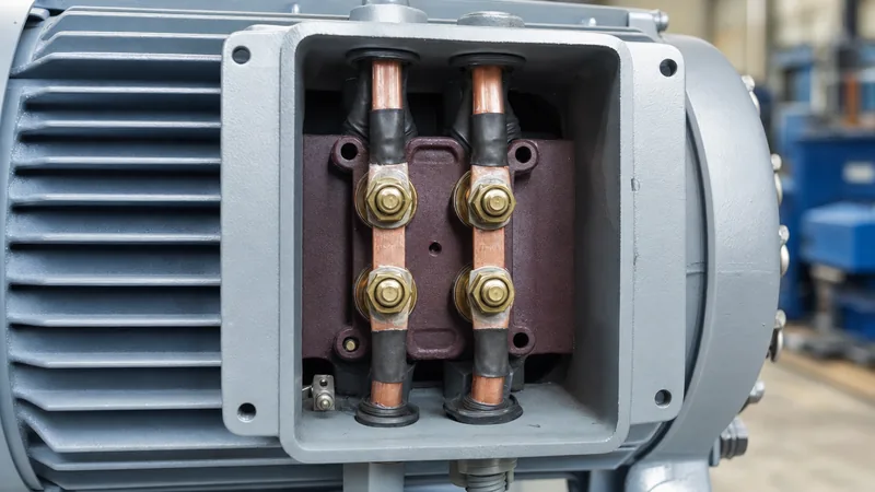
Industrial three-phase induction motors standardise terminal labelling using IEC 60034-8 or NEMA MG-1 specifications to enable simple conversion between wye and delta. The standard IEC motor connection box presents six terminals arranged in two rows of three terminals: the top row contains W2, U2, and V2, while the bottom row contains U1, V1, and W1.
Follow this exact technical procedure to bridge the motor terminal block for delta operation:
- Isolate and verify dead: De-energise upstream power at the switchgear breaker, lock out and tag out (LOTO), and verify zero potential across all phases using a calibrated high-voltage multi-meter.
- Inspect terminal markings: Identify the physical layout. Notice that the top terminals are intentionally offset relative to the bottom row (W2 sits directly opposite U1; U2 sits opposite V1; V2 sits opposite W1).
- Position the terminal jumpers: Install three copper jumper links parallel to one another in the vertical direction. Bridge terminal W2 to U1 with the first link, terminal U2 to V1 with the second link, and terminal V2 to W1 with the third link.
- Torque connection hardware: Tighten terminal nuts to the manufacturer-specified torque rating (typically 4 Nm for M5 studs, 6 Nm for M6 studs, and 10 Nm for M8 brass studs) to prevent high-resistance thermal hotspots.
- Connect incoming phase leads: Bolt supply line cable L1 to terminal U1, line cable L2 to terminal V1, and line cable L3 to terminal W1. Verify that the protective earth (PE) conductor bonds securely to the motor frame grounding terminal.
Mathematical relationships and phase angles in delta coils
In a balanced delta-connected motor winding, the vector summation of phase voltages and line currents follows fundamental sinusoidal alternating current laws. Because each coil connects directly between two lines, the magnitude of phase voltage equals line voltage:
Vph = VL
However, the line current entering any given corner junction divides between two separate winding phases. Applying Kirchhoff’s Current Law (KCL) at node U1 shows that line current IL1 equals phase current IU minus phase current IW. Because the phase currents are separated by 120 electrical degrees, the vector calculation yields:
IL = √3 × Iph ≈ 1.732 × Iph
Total three-phase apparent power (S in kVA) and active electrical power (P in kW) consumed by a delta connected motor are calculated identically to a wye motor using line values:
P = √3 × VL × IL × cos(φ)
Here, cos(φ) represents the operating power factor. For deeper analysis of line-to-line relationships and vector summation across upstream supplies, refer to our detailed technical guide on 3-phase voltage explained.
Torque, current, and the star-delta starting cycle
A star-delta starting sequence temporarily arranges motor coils in star to reduce electrical inrush current before switching them permanently into a delta coil arrangement for full-load running. Direct-on-line (DOL) starting of a motor in delta arrangement draws between 600% and 800% of full-load rated current, which can provoke excessive thermal stress in windings and voltage drop across upstream oil-immersed transformers.
Because torque in an induction motor is proportional to the square of the voltage across its phase coils (T ∝ Vph2), running in star reduces winding voltage to 57.7% of line voltage. Squaring 0.577 yields precisely 0.333, or one-third. Therefore, during the initial star-starting phase:
- Starting line current is reduced to 33% of the delta locked-rotor current.
- Starting torque is reduced to 33% of the delta locked-rotor torque.
Once the motor accelerates to approximately 75% to 85% of synchronous speed, a timer inside the motor starter opens the star contactor and closes the delta contactor. This transition reapplies full line voltage across each coil, restoring full operating torque capability and allowing the drive system to meet rated process output.
Diagnosing faults in delta motor coil arrangements
Diagnosing an electrical fault in a delta arrangement requires removing the terminal jumper links because the closed loop conceals open circuits and earth faults during routine continuity checks. If resistance is measured across the terminals with jumpers intact, a meter reading across any single phase measures that phase in parallel with the series combination of the other two phases, distorting the reading.
To perform accurate diagnostic testing under standard maintenance protocols:
- Uncouple the jumpers: Disconnect all three jumper bars to isolate phase coils U1–U2, V1–V2, and W1–W2 completely.
- Winding resistance testing: Measure DC resistance of each individual phase using a digital micro-ohmmeter. Per IEEE 118 standards, the resistance variance among the three phases should not exceed 2% to 3%. A high resistance indicates loose internal brazing or partial open circuit.
- Insulation resistance (megohmmeter): Test insulation integrity between each coil and ground (motor frame) and between adjacent phases (U-V, V-W, W-U) using a 500V or 1000V DC test voltage. Per IEEE 43, readings should exceed 100 MΩ on modern Class F insulation systems.
- Symmetrical phase currents: During uncoupled no-load testing, verify that current in all three supply lines remains balanced within 5%. Severe unbalance in a delta motor indicates inter-turn shorts or significant line voltage distortion.
Next steps: specifying and sourcing
When specifying electric motors, heavy industrial drives, and upstream power equipment, electrical engineers must coordinate motor winding arrangements with substation voltage ratings and transformer secondary configurations. Supplying large delta-connected motors requires carefully calculated fault limits, robust short-circuit withstand capabilities, and low-loss distribution equipment.
Our engineering design team manufactures high-efficiency dry-type transformers, rugged oil-immersed transformers, and factory-integrated medium-voltage switchgear engineered to IEC 60076 and IEEE C57.12 standards. To request system sizing calculations, vector group recommendations, or a comprehensive project equipment quotation, submit your electrical single-line diagram and load schedule directly via our transformer quotation page.
Frequently asked questions
what is the coil arrangement in a delta connected motor
The coil arrangement in a delta connected motor links three stator phase windings head-to-tail in a continuous triangular loop. Each connection point between two coils connects directly to an incoming AC line phase, placing full line voltage across each individual winding coil.
Why does a delta motor not have a neutral wire?
A delta motor does not have a neutral wire because its three coils form a closed mesh circuit with no central common junction point. Current continuously circulates between the three active phase lines, balancing symmetrically across the 120-degree phase displacements without requiring a return path.
Can you run a delta-wound motor on a wye supply?
Yes, a delta-wound motor operates normally from a wye-configured transformer secondary provided the line-to-line voltage matches the motor delta nameplate voltage. The motor simply connects to the three phase lines (L1, L2, L3) and leaves the transformer neutral conductor unconnected.
What happens if one coil opens in a delta connected motor?
If one coil burns open in a delta motor, the motor continues running on the remaining two coils in an open-delta configuration under severely degraded conditions. Operating capacity drops to 57.7% of normal rating, line currents become highly unbalanced, and the motor will rapidly overheat if fully loaded.
How do you identify a delta motor from its nameplate?
A motor nameplate indicates delta configuration using the triangle symbol (Δ) alongside its rated line voltage and current, such as 'Δ 400V 28A'. Dual-voltage nameplates often list 'Δ/Y 230/400V', indicating the coils must be bridged in delta for 230V line supplies and wye for 400V supplies.
Tags: delta connected motor coil arrangement wye diagram motor winding three phase motor


