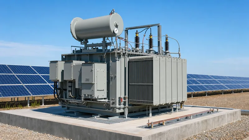
Key takeaways
- A solar power transformer steps up inverter AC output voltages (typically 600 V to 800 V) to medium-voltage collection levels between 11 kV and 34.5 kV.
- Harmonic currents from pulse-width modulation inverters generate elevated eddy current losses, requiring K-factor design (K-4 to K-9) under IEEE C57.110.
- Dual-inverter step-up units use split low-voltage windings with dedicated electrostatic shields to isolate inverter pairs and suppress high-frequency transient capacitive coupling.
- Extreme thermal cycling caused by solar irradiance fluctuations stresses winding insulation, necessitating mineral oil or synthetic ester cooling optimised for ambient temperatures up to 50 °C.
- Direct-current bias from inverter modulation must be mitigated through conservative core flux density sizing (typically below 1.6 Tesla) to avoid core saturation.
Quick answer: A solar power transformer is a specialised step-up transformer engineered to interface photovoltaic inverters with the medium-voltage collection network, converting low AC inverter voltages (typically 600 V to 800 V) up to 11 kV, 22 kV, or 34.5 kV. Designed in accordance with IEEE C57.159, these units withstand intense daily thermal cycling, significant harmonic distortion, and direct-current bias originating from solid-state switching circuits.
Utility-scale photovoltaic (PV) generation introduces distinct electrical operating conditions absent from conventional thermal or hydroelectric generation facilities. While a traditional distribution transformer experiences relatively steady diurnal load curves, solar transformers endure abrupt ramp rates, peak-load operating regimes concurrent with maximum ambient solar irradiance, and inverted power flow patterns. Modern solar installations demand transformers built to survive non-sinusoidal waveforms without premature dielectric or thermal breakdown, directly affecting the lifetime levelised cost of electricity (LCOE).
Achieving system reliability requires precise coordination between the inverter pulse-width modulation (PWM) profile, the transformer core-and-coil assembly, and medium-voltage switchgear. In this guide, our engineering team examines the physical stresses, winding configurations, derating calculations, and standard specifications governing industrial-grade solar step-up transformers.
What Is a Solar Power Transformer and How Does It Operate?
A solar power transformer operates as a generation step-up (GSU) asset positioned adjacent to solar inverter stations to elevate low-voltage inverter AC outputs to medium-voltage distribution circuits. In utility-scale solar farms, central inverters convert direct current from PV strings into low-voltage alternating current, most commonly 600 V, 690 V, or 800 V three-phase AC. The solar power transformer receives this low-voltage power and transforms it to intermediate collection voltages between 11 kV and 34.5 kV, transmitting bulk power across the site collector system toward the main substation as detailed in our guide to grid integration of renewable energy sources.
Unlike standard equipment, solar transformers function under intermittent load factors determined entirely by meteorological patterns. Operation begins at dawn with zero-voltage energisation, transitions through rapid thermal loading as solar irradiance peaks during midday, and drops back to zero load at dusk. During zero-load night periods, the transformer remains energised under no-load conditions from the grid, continuously drawing core excitation losses unless disconnected by medium-voltage switchgear. Consequently, core design must minimise no-load losses (iron losses) to maintain project economics, while winding structures must resist mechanical stresses caused by daily thermal expansion and contraction cycles.
Solar Transformers vs Conventional Distribution Transformers
Solar transformers differ fundamentally from conventional distribution units in their thermal duty profile, harmonic endurance, and electrostatic isolation requirements. Standard commercial distribution units assume sinusoidal currents with a Total Harmonic Distortion (THD) under 5% and operate under steady, predictable commercial or residential load profiles. In contrast, inverter step-up transformers face continuous harmonic injection from high-frequency inverter switching, requiring reinforced insulation and oversized neutral paths.
| Operational Parameter | Conventional Distribution Unit | Solar Power Transformer |
|---|---|---|
| Primary Load Direction | Unidirectional (Medium to Low Voltage) | Unidirectional Step-Up (Low to Medium Voltage) |
| Input Waveform | Sinusoidal (THD < 5%) | Non-sinusoidal (PWM switched, THD up to 8-12% pre-filter) |
| Harmonic K-Factor Rating | K-1 (Standard) | K-4 to K-9 (Reinforced windings) |
| Core Flux Density Design | 1.70 to 1.75 Tesla | 1.55 to 1.62 Tesla (Prevents DC saturation) |
| Low-Voltage Windings | Single LV winding | Often split dual or quad LV windings |
| Electrostatic Ground Shield | Rarely specified | Mandatory between LV and HV winding groups |
| Daily Thermal Cycling | Gradual curve, 40-70% average load | 0% to 100% full thermal swings daily |
Furthermore, standard distribution systems do not experience the direct-current (DC) injection that can leak from solid-state inverter bridges. In a solar power transformer, even minor DC current injection (e.g., < 0.5% of rated current) pushes the magnetic core toward asymmetrical half-cycle saturation, resulting in elevated audible noise, excessive stray flux heating in structural steel, and increased excitation current. Addressing this requires lower operating flux density thresholds during magnetic core fabrication.
Inverter Harmonics, K-Factor, and Thermal Sizing Calculations
Harmonic currents generated by inverter switching significantly increase transformer internal losses, primarily through winding eddy current losses and stray load losses in the tank walls and core clamps. Calculating the required harmonic derating involves establishing the transformer harmonic loss factor ($F_{HL}$) or specifying an appropriate K-factor in accordance with IEEE C57.110 (Recommended Practice for Establishing Liquid-Filled and Dry-Type Power and Distribution Transformer Capability When Supplying Nonsinusoidal Load Currents).
Winding eddy current losses scale with the square of the harmonic frequency ($h^2$). Without proper derating, hot-spot temperatures rise rapidly, degrading the solid cellulose insulation and dramatically shortening the operating lifespan, as outlined in our winding temperature transformer guide. The standard K-factor equation is defined as:
K = Σ [ Ih / I1 ]2 × h2
Where Ih is the root-mean-square current at harmonic order h, and I1 is the fundamental 50 Hz or 60 Hz current. Consider a worked engineering calculation for a 3,125 kVA, 800 V inverter step-up unit operating on a central inverter skid:
- Rated fundamental phase current ($I_1$): 2,255.4 A at 800 V
- Dominant harmonic profile: 5th harmonic (3.2%), 7th harmonic (2.1%), 11th harmonic (1.4%), 13th harmonic (0.9%)
- Summation of $I_h^2 \times h^2$ results in an operational K-factor of 3.42
- Specified design rating: K-4 minimum (standard margin to allow for inverter aging and high ambient conditions)
If standard winding conductor geometries were used under this profile, winding eddy current losses ($P_{EC}$) would increase by 242% over nominal sinusoidal values. To control internal heat rise, the manufacturer must implement multi-strand continuously transposed conductors (CTC) or thin copper foil strips, reducing individual strand dimensions below the skin depth of the higher harmonic components.
Dual-LV Windings and Electrostatic Shielding Design
Split-winding configurations are widely adopted in utility-scale solar generation to enable two or more separate central inverters to connect to a single step-up transformer without parallel coupling on the low-voltage AC bus. In a dual-LV transformer (e.g., Dy11-y11 or Dy1-y1), two electrically isolated low-voltage windings are wound concentrically or axially alongside a single high-voltage winding connected to the collector grid. This topology halves the number of physical transformers required across the site, lowering foundation, civil, and maintenance expenditures.
Maintaining high cross-impedance between the two low-voltage windings (typically achieving cross-winding decoupling impedance $\ge 1.5 \times Z_{HV-LV}$) is vital. High internal galvanic isolation prevents circulating carrier currents, prevents cross-talk between the inverter control loops, and reduces short-circuit fault levels if an arc flash occurs at one inverter terminal. Refer to our engineering review on transformer connections and vector groups for winding displacement specifications.
Furthermore, grounded electrostatic shielding is mandatory between the low-voltage and high-voltage windings. The electrostatic shield consists of an unclosed copper sheet placed between the inner and outer winding coils, earthed directly to the main transformer tank earthing terminal. This shield fulfills three key functions:
- Prevents high-frequency switching transients generated by PWM inverters from capacitive transfer onto the medium-voltage grid.
- Protects sensitive inverter semiconductor bridges (IGBTs) from line-side medium-voltage lightning surges and switching impulses.
- Attenuates common-mode electrical noise between medium-voltage and low-voltage systems in accordance with IEEE C57.159 clause 5.4.
Technical Specification Checklist for Utility-Scale PV Transformers
An engineer preparing a formal Request for Quotation (RFQ) for solar transformers must define mechanical, electrical, and thermal parameters beyond basic kVA capacity. Solar farms are frequently built in high-ambient, arid environments, such as deserts, where daytime temperatures regularly exceed 45 °C and solar radiation adds significant thermal burden.
| Specification Item | Standard Requirement / Recommendation | Design Purpose |
|---|---|---|
| Applicable Standards | IEC 60076-16 / IEEE C57.159 | Ensures compliance with wind and solar generation step-up duty |
| Insulating Fluid | Inhibited Mineral Oil (IEC 60296) or Synthetic Ester (IEC 61099) | Esters provide high fire points (>300 °C) and bio-degradability |
| Ambient Temperature Range | -25 °C to +50 °C (Peak) | Addresses high solar ambient environments without premature derating |
| Top Oil / Winding Temp Rise | 50 °C / 55 °C rise limits (above ambient) | Conservative limits compensate for 50 °C site conditions |
| Core Flux Density | ≤ 1.60 Tesla at nominal voltage | Prevents saturation caused by DC offset from inverter switching |
| Harmonic K-Factor | K-4 minimum; K-7 to K-9 for high THD inverters | Compensates for high-frequency eddy losses in copper conductors |
| Short-Circuit Impedance (%Z) | 6.0% to 8.5% (Tolerances per IEC 60076-1) | Limits fault currents to match switchgear breaking ratings |
| Basic Impulse Insulation (BIL) | 95 kV to 200 kV crest (per system MV class) | Guards against site atmospheric lightning surges |
| Tank Corrosion Class | C4 or C5 High (ISO 12944-2) | Prevents premature rust in harsh desert or coastal environments |
To integrate seamlessly into utility infrastructure, transmission-level interconnections require alignment with the broader network; review our transmission transformer guide for higher-voltage substation interfaces.
Installation, Testing, and Commissioning Considerations
Commissioning a solar power transformer requires targeted site verification to ensure the unit withstands inverter-driven stresses prior to commercial operation. Due to the high financial costs associated with plant outages during peak daylight hours, factory acceptance testing (FAT) and pre-energisation site tests must follow rigorous quality standards.
- Perform Insulation Resistance and Polarisation Index: Measure high-voltage to low-voltage, high-voltage to earth, and low-voltage to earth resistance using a 2.5 kV or 5 kV insulation tester. The 10-minute to 1-minute Polarisation Index (PI) ratio must exceed 1.5 for mineral-oil units under IEEE C57.152.
- Verify Electrostatic Shield Continuity: Conduct resistance checks between the copper electrostatic shield grounding lead and the main transformer enclosure, confirming direct low-resistance contact (< 0.1 Ω) without ground loops.
- Measure Winding Ratio and Vector Displacement: Verify transformer turns ratios across all tap positions using a Three-Phase TTR meter, ensuring ratio error remains well within the ±0.5% tolerance defined by IEC 60076-1 clause 9.3.
- Execute Sweep Frequency Response Analysis (SFRA): Establish a baseline fingerprint curve of the core and coil assembly to detect any core shifting or winding deformation that may have occurred during container ocean transport or overland rough-road transit.
- Perform Fluid Dielectric Breakdown and Moisture Testing: Draw insulating liquid samples from the bottom drain valve to confirm dielectric breakdown strength exceeds 50 kV (per IEC 60156) and moisture content remains below 15 ppm before energisation.
- Verify Thermal and Pressure Protection Signals: Trip-test top-oil temperature indicators, winding temperature simulators, sudden pressure relays, and the Buchholz relay back to the medium-voltage breaker trip circuit.
Next steps: specifying and sourcing
When specifying a solar power transformer for your next photovoltaic project, assemble your system parameters including inverter rated AC voltage, total harmonic spectrum (THD), maximum ambient site temperatures, vector group requirements, and preferred cooling methods (ONAN or KNAN). To explore robust field solutions, review our heavy-duty pad-mounted transformers and utility-scale oil-immersed transformers engineered specifically for utility-scale solar generation. For integrated plug-and-play balance-of-plant packages, examine our prefabricated transformer substations. Contact our engineering and tendering team via our quotation page or reach out through our contact desk to receive detailed general arrangement drawings, thermal loss calculations, and commercial tenders tailored to your regional grid code requirements.
Frequently asked questions
Why does a solar power transformer require a K-factor rating?
A solar power transformer requires a K-factor rating to handle non-sinusoidal currents and harmonic frequencies produced by inverter switching. These harmonics cause severe winding eddy current losses and stray overheating. A rating of K-4 to K-9 ensures the copper windings and structural insulation withstand this heat without premature degradation.
What is the role of the electrostatic shield in a solar transformer?
The electrostatic shield prevents high-frequency capacitive transient coupling between the inverter low-voltage windings and the medium-voltage grid. It protects sensitive inverter semiconductors from transmission surges while simultaneously blocking common-mode inverter switching noise from polluting the utility distribution network.
Can a standard distribution transformer be used for solar power plants?
A standard distribution transformer should not be used in solar plants without significant derating and engineering modifications. Conventional units lack electrostatic shielding, are vulnerable to harmonic overheating, and cannot accommodate the continuous DC bias and daily thermal cycling inherent to photovoltaic inverter systems.
Why are dual low-voltage windings used in solar transformers?
Dual low-voltage windings allow two separate central inverters to connect to a single transformer without direct electrical paralleling. This configuration halves civil foundation and equipment footprints while providing high cross-impedance that eliminates circulating carrier currents between the inverter power stages.
How does ambient temperature affect solar power transformer sizing?
Ambient temperature directly dictates transformer sizing because peak solar generation occurs simultaneously with peak solar heat radiation. Transformers installed in desert climates reaching 45 °C to 50 °C ambient must be engineered with lower winding temperature rise limits (such as 50 °C or 55 °C) to prevent thermal degradation.
What core flux density is recommended for solar step-up transformers?
Operating core flux density is typically specified below 1.60 Tesla for solar step-up transformers. This conservative threshold prevents magnetic saturation resulting from small direct-current (DC) offsets generated by inverter pulse-width modulation, preventing core overheating and high excitation currents.
Tags: solar power transformer solar transformers photovoltaic transformer step-up transformer inverter transformer


