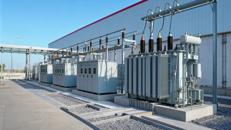
Key takeaways
- Primary power distribution voltages typically span from 11 kV to 34.5 kV in medium-voltage grids, stepping down to secondary utilization levels between 120 V and 690 V.
- IEC 60038 defines international standard voltages including 400 V/230 V three-phase systems, whereas ANSI C84.1 governs North American networks with 480Y/277 V and 208Y/120 V configurations.
- Distribution line voltage selection directly determines line losses, where doubling line voltage reduces load current and I²R resistive losses by 75% for identical delivered apparent power.
- System insulation coordination relies on rated Basic Impulse Level (BIL) ratings, which scale from 75 kV to 170 kV BIL for distribution equipment between 11 kV and 34.5 kV nominal levels.
- Voltage regulation standards mandate that steady-state service voltages remain within Range A tolerances (+/-5%) under normal operating conditions to prevent motor stall or insulation breakdown.
Quick answer: Standard power distribution voltages are classified into medium-voltage (MV) primary lines (typically 11 kV to 34.5 kV) and low-voltage (LV) secondary lines (120 V to 690 V). They deliver bulk electrical energy from regional transmission substations down to end-user equipment while maintaining regulated voltage tolerances established by IEC 60038 and ANSI C84.1.
Distribution networks form the final stage of electrical power delivery. Power leaves generating stations at transmission levels (110 kV to 765 kV) and steps down at bulk distribution substations. The primary distribution network routes electricity through urban and rural corridors using overhead conductors or underground cables to feed local distribution transformers. These transformers step down the medium voltage to secondary utilization levels for industrial machinery, commercial services, and residential panels.
Selecting the correct nominal distribution system voltage influences conductor sizing, switchgear interrupting capacity, dielectric insulation levels, transformer winding configurations, and operational energy efficiency. Understanding global voltage standards and distribution topology is vital when specifying equipment for modular substations, factory switchboards, and utility tie-ins.
Standard Distribution System Voltage Classifications: ANSI vs IEC
A distribution system voltage is governed globally by two primary standardization frameworks: ANSI C84.1 in North America and IEC 60038 across Europe, Asia, Africa, and Australasia. These standards classify distribution into low-voltage, medium-voltage, and high-voltage bands, defining both nominal voltages and allowable operational limits.
ANSI C84.1 designates voltages up to 1,000 V as low voltage, voltages from 1 kV through 34.5 kV as medium voltage, and voltages above 34.5 kV to 230 kV as high voltage. The standard establishes two operating bands: Range A (normal service conditions, typically +/-5% of nominal at the service point) and Range B (infrequent emergency conditions permitting -8.3% to +5.8%). In contrast, IEC 60038 sets low voltage up to 1,000 V AC (1,500 V DC) and medium voltage from 1 kV up to 35 kV. IEC networks generally operate on a +/-10% steady-state voltage tolerance at low-voltage delivery points.
Medium-voltage networks built to IEC standards standardise around 11 kV, 22 kV, and 33 kV for primary three-phase distribution. ANSI networks commonly implement 12.47Y/7.2 kV, 13.8 kV, 24.94Y/14.4 kV, and 34.5Y/19.92 kV systems. To explore equipment configurations accommodating both low and medium-voltage standards, consult our electric power distribution engineering guide.
Primary Distribution Line Voltage Levels and Grid Topologies
A distribution line voltage operating at medium voltage supplies power from distribution substations to pad-mounted, pole-mounted, or compact box-type substations. System planners select specific primary levels based on feeder distance, load density, and right-of-way constraints.
Feeder topologies fall into two common medium-voltage configurations: three-wire ungrounded/resistance-grounded delta or four-wire multigrounded wye systems. North American utilities widely use four-wire wye circuits (such as 13.2Y/7.62 kV or 12.47Y/7.2 kV), which allow single-phase pole transformers to connect between one phase conductor and the multi-grounded neutral line. European and Commonwealth grids predominantly employ three-wire 11 kV or 33 kV systems derived from delta-connected or impedance-grounded wye transformer windings. For details on how medium-voltage equipment isolates and protects these feeders, see our MV switchgear engineering guide.
Higher primary distribution voltages (e.g., 33 kV or 34.5 kV) transmit power four to eight times farther than an 11 kV line for the same conductor cross-section and allowable percentage voltage drop. However, higher voltages demand larger electrical clearances, higher basic impulse insulation levels (BIL), and costlier medium-voltage switchgear.
Secondary Distribution Voltages for Industrial and Commercial Sites
Secondary distribution delivers power directly to facility main distribution switchboards at utilization voltages below 1,000 V. The choice between delta and wye secondary topologies dictates phase-to-phase and phase-to-neutral options available to downstream circuits.
In IEC-compliant markets, the standard three-phase four-wire secondary distribution system voltage is 400Y/230 V at 50 Hz. Three-phase motors and industrial plant equipment connect across lines at 400 V line-to-line, while building lighting and single-phase domestic receptacles operate at 230 V line-to-neutral. Heavy industrial installations with large drives often incorporate dedicated 690 V secondary networks to reduce motor cable sizing and starter costs.
In North America, commercial and industrial complexes run primarily on 480Y/277 V, three-phase, four-wire at 60 Hz. The 480 V line-to-line voltage supplies industrial heating, chillers, and large three-phase variable frequency drives, whereas 277 V line-to-neutral supplies commercial LED lighting circuits. Dry-type step-down transformers then establish separate 208Y/120 V secondary networks for computers, convenience receptacles, and office appliances. Prefabricated arrangements that integrate step-down transformers with low-voltage distribution boards are detailed in our unit substation engineering guide.
Equipment Sizing and Insulation Ratings by Voltage Class
Electrical switchgear, disconnect switches, and transformers require ratings that match the maximum continuous operating voltage and withstand system transient overvoltages. IEEE C57.12.00 Table 4 and IEC 60076-3 specify maximum operating equipment voltage (Um), power-frequency withstand voltage, and rated Basic Impulse Level (BIL).
The table below compares standard medium- and low-voltage ratings for distribution transformers, ring main units (RMUs), and switchgear lineups across industrial distribution systems:
| Nominal System Voltage (kV) | Standard Reference | Maximum Voltage Um (kV) | Impulse Withstand BIL (kV Peak) | Power Frequency Withstand (kV RMS) | Common Industrial Application |
|---|---|---|---|---|---|
| 0.400 / 0.230 | IEC 60038 | 1.1 | 8 | 3 | Commercial/industrial low-voltage supply |
| 0.480 / 0.277 | ANSI C84.1 | 0.6 | 10 | 2.2 | North American industrial motor control centers |
| 11.0 / 6.35 | IEC 60038 | 12.0 | 75 / 95 | 28 | Primary city rings & industrial parks |
| 13.8 / 7.97 | ANSI C84.1 | 15.0 / 15.5 | 95 / 110 | 34 | Utility feeders & continuous process plants |
| 22.0 / 12.7 | IEC 60038 | 24.0 | 125 | 50 | Suburban distribution & heavy fabrication |
| 33.0 / 19.05 | IEC 60038 | 36.0 | 170 | 70 | Renewable collector feeds & long rural links |
| 34.5 / 19.92 | ANSI C84.1 | 38.0 | 150 / 200 | 80 | Wind/solar park collectors & mining feeds |
Selecting equipment requires coordinating the nominal line voltage with the appropriate BIL level. For instance, coastal areas, lightning-prone zones, or installations tied directly to overhead lines require upgraded BIL ratings (e.g., selecting 110 kV BIL rather than 95 kV for a 15 kV switchgear class) to prevent dielectric flashover under lightning surges. For more on enclosure design and switchgear busbar architecture, see our electrical switchgear guide.
Distribution Line Voltage Drop and Conductor Sizing Calculation
Calculating steady-state voltage drop confirms that the delivered distribution system voltage remains within statutory tolerances under peak load conditions. Excessive voltage drop causes motor overheating, contactor drop-out, and nuisance trips of electronic power converters.
For a balanced three-phase AC feeder, line-to-line voltage drop (Vdrop) is calculated using the formula: Vdrop = √3 × I × L × (R × cos(θ) + X × sin(θ)), where I is line current in amperes, L is circuit length in kilometres, R is conductor AC resistance in Ω/km at operating temperature, X is inductive reactance in Ω/km, and cos(θ) is the load power factor.
Consider a practical engineering calculation for a 13.8 kV primary distribution line voltage supplying an industrial facility:
- Feeder Apparent Power (S): 5,000 kVA (5 MVA)
- Nominal Voltage (VLL): 13,800 V (13.8 kV)
- Feeder Length (L): 3.2 km underground copper cable
- Load Power Factor: 0.85 lagging (cos θ = 0.85; sin θ = 0.527)
- Conductor Selected: 3/C 185 mm² Cu XLPE cable (R = 0.128 Ω/km, X = 0.105 Ω/km at 90°C)
Step 1: Calculate full-load line current (I):
I = S / (√3 × VLL) = 5,000,000 VA / (1.732 × 13,800 V) = 209.18 A
Step 2: Calculate unit impedance drop component:
(R × cos θ) + (X × sin θ) = (0.128 × 0.85) + (0.105 × 0.527) = 0.1088 + 0.0553 = 0.1641 Ω/km
Step 3: Calculate total three-phase voltage drop (Vdrop):
Vdrop = 1.732 × 209.18 A × 3.2 km × 0.1641 Ω/km = 190.28 V
Step 4: Determine the percentage voltage drop (%Vdrop):
%Vdrop = (190.28 V / 13,800 V) × 100% = 1.38%
Because 1.38% is well below the standard 3.0% maximum allowable drop for medium-voltage primary feeders (per IEEE Std 141 Red Book recommendations), the conductor size is technically compliant. The receiving voltage remains at 13,609.7 V, falling well inside ANSI C84.1 Range A limits.
Specifying Transformer Taps and Voltage Regulation in Compact Substations
Transformer winding taps compensate for steady-state variations in incoming distribution line voltage. Because utility distribution feeders experience changing loading between peak and off-peak hours, transformers rely on taps to maintain standard secondary voltage.
Distribution transformers are routinely equipped with a De-Energized Tap Changer (DETC) on the high-voltage winding, governed by IEC 60076-1 clause 5.4 or IEEE C57.12.00. The standard configuration provides five tap positions in 2.5% increments: +5.0%, +2.5%, nominal (0%), -2.5%, and -5.0%. When primary distribution line voltage regularly sags below nominal due to line resistance over long distances, operators switch the DETC to the -5% tap. This reduces the primary turns count, restoring secondary output to 400 V or 480 V.
To guarantee reliability in prefabricated and box-type substations, verify the following tap changer and voltage regulation requirements during technical procurement:
- Confirm tap adjustment mechanism: Manual off-circuit de-energized switch with padlockable handle, or motorized On-Load Tap Changer (OLTC) for installations feeding voltage-sensitive loads.
- Specify primary tap range based on utility interconnect studies (e.g., +/-2 × 2.5% for standard networks or +/-4 × 2.5% for extended rural lines).
- Verify enclosure clearance and oil/insulation barrier ratings to satisfy BIL specs at the lowest tap setting, where volts-per-turn is highest.
- Require ratio test verification across all tap positions during factory acceptance tests (FAT) per IEC 60076-1 clause 11.3.
Next steps: specifying and sourcing
Specifying the optimal equipment for primary and secondary power distribution voltages requires precise alignment between utility interconnect standards, short-circuit current capacities, and load profiles. When preparing your request for quotation, compile your single-line diagrams, incoming nominal voltage, BIL requirements, short-circuit withstand levels, and site environmental classifications.
Our factory manufactures integrated transformer substations, robust HV and LV switchgear, and outdoor pad-mounted transformers custom-engineered to IEC and ANSI standards. Submit your project requirements to our application engineers via our quote request page or reach out through our contact page to receive a comprehensive technical proposal and tender schedule.
Frequently asked questions
What is the difference between transmission and power distribution voltages?
Transmission voltages range from 110 kV to 765 kV and carry bulk electrical power over hundreds of kilometres between generating plants and load regions. Power distribution voltages range from 110 V up to 35 kV, stepping power down through substations to safely deliver electricity to industrial, commercial, and residential facilities.
Why is 11 kV or 13.8 kV used for primary distribution instead of low voltage?
Medium distribution line voltages reduce resistive power losses and conductor material requirements. Transmitting 5 MW of power at 400 V requires 7,217 A of current, whereas at 11 kV it requires only 262 A. Because resistive losses scale with the square of current (I²R), transmitting at medium voltage reduces line losses by roughly 99.8%.
What are the common distribution system voltage levels in North America versus Europe?
North American primary distribution commonly utilizes 12.47 kV, 13.8 kV, 24.94 kV, and 34.5 kV wye systems, with 480Y/277 V and 208Y/120 V secondary levels. European systems predominantly run on 11 kV, 22 kV, and 33 kV three-wire primary networks, delivering a standard 400Y/230 V three-phase secondary supply.
How does power factor affect distribution voltage drop?
A lagging power factor significantly increases voltage drop across a distribution line. Because AC overhead lines and underground cables have substantial series inductive reactance, the reactive component of the current (I × sin θ) produces a quadrature voltage drop that compounds the in-phase resistive drop, lowering the delivery voltage.
What is the acceptable voltage variation for a commercial distribution system?
Under ANSI C84.1 Range A, steady-state delivery voltage should remain within +/-5% of nominal under standard operation. IEC 60038 specifies an operating tolerance of +/-10% for low-voltage systems. Voltages outside these bands risk causing electric motor overheating, nuisance trips of electronic drives, and premature equipment failure.
Tags: power distribution voltages distribution system voltage distribution line voltage medium voltage low voltage


