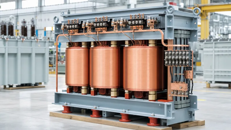
Key takeaways
- A standard static three phase to one phase transformer cannot draw balanced current from all three supply lines to feed a single purely single-phase load.
- Deriving single-phase power from a three-phase system is most simply achieved by connecting line-to-neutral or line-to-line, but this concentrates load on individual phases.
- The Scott-T transformer connection converts a balanced three-phase supply into a balanced two-phase supply, which can supply two isolated single-phase loads of identical rating.
- Open-delta and special magnetic core topologies like Le Blanc transformers distribute unbalanced single-phase loads across three phases in fixed 1:2:1 or 1:1:2 current ratios.
- True balanced three-phase to single-phase AC conversion without network unbalance requires a power conversion system utilising an active rectifier and inverter DC bus.
Quick answer: A three phase to one phase transformer transforms electrical energy between three-phase supply lines and single-phase loads, but passive electromagnetic transformation cannot draw balanced currents from all three phases into a single ungrounded resistive or inductive load without intermediate phase splitting, rotating machinery, or power electronic conversion.
Industrial facilities frequently encounter challenges when heavy single-phase equipment—such as resistance welders, large high-frequency induction furnaces, or specialized testing benches—must run on three-phase infrastructure. Connecting large single-phase loads across three-phase distribution systems causes voltage imbalance, neutral overheating, and upstream generator de-rating. Engineers must understand how to navigate the technical constraints of magnetic phase transformation, evaluate winding configurations, and determine when a transformer or an active electronic solution is required.
Can you convert 3 phase to single phase?
Yes, you can convert three-phase supply to single-phase power, but electromagnetic laws dictate that power drawn by a single alternating phase fluctuates cyclically from zero to peak, whereas balanced three-phase power delivers constant instantaneous energy. Because a static, passive transformer stores minimal instantaneous energy in its magnetic core, it cannot mathematically or physically convert a constant three-phase power delivery into a single pulsating alternating-current output without creating an unbalanced draw on the supply lines.
According to IEEE C57.12.00 Clause 5.10 and IEC 60076-1, phase balance requires equal current magnitude across all three phases with exactly 120-degree displacement. When supplying single-phase power directly from a three-phase line, engineers utilise four principal methods:
- Direct Line-to-Neutral tap: Connecting a load between one phase conductor and the system neutral yields standard phase voltage (for example, 230 V from a 400 V wye network, or 120 V from a 208V 3 phase power system).
- Direct Line-to-Line tap: Connecting across two phase legs yields phase-to-phase voltage (such as 400 V or 480 V from a 480V 3 phase power network), utilizing two primary conductors while the third carries zero current.
- Special magnetic connections: Using a specialized three phase to one phase converter transformer configuration, such as an open-delta, Le Blanc, or modified Scott-T assembly, to distribute the single-phase output over two or three upstream phases.
- Solid-state conversion: Utilizing an active rectifier and inverter topology governed by a modern power conversion system to pull balanced three-phase currents, rectify them to a DC bus, and invert the output to single-phase AC.
How to get single phase from three phase using transformer configurations
The choice of transformation topology depends on whether the secondary side requires electrical isolation, balanced load splitting, or simple voltage stepping. Connecting single-phase loads incorrectly can exceed voltage unbalance limits, which NEMA MG 1 specifies must remain below 1% to prevent severe motor de-rating.
Below is an engineering comparison of the primary topologies used to achieve conversion of 3 phase to single phase power:
| Configuration | Input Phases Used | Primary Phase Balance | Secondary Isolation | KVA Utilization Factor |
|---|---|---|---|---|
| Line-to-Neutral Direct | 1 Phase + Neutral | Completely Unbalanced (1:0:0) | No (Direct Galvanic) | 1.00 |
| Line-to-Line Direct | 2 Phases | Unbalanced (1:1:0) | No (Direct Galvanic) | 1.00 |
| Isolation Transformer (1-Phase Core) | 2 Phases | Unbalanced (1:1:0) | Yes (Galvanic) | 1.00 |
| Scott-T Connection (Two Loads) | 3 Phases | Balanced (if loads match) | Yes (Galvanic) | 0.866 |
| Le Blanc Transformer | 3 Phases | Semi-balanced (1:2:1 ratio) | Yes (Galvanic) | 0.866 |
| Open-Delta (V-V) Assembly | 3 Phases (2 Cores) | Partially Unbalanced | Yes (Galvanic) | 0.577 |
For dedicated step-down requirements where galvanic isolation is necessary, engineers often specify a customized single phase transformer connected across two phases of the supply system. This ensures that the single-phase load does not return high harmonic currents via a shared utility neutral conductor.
Scott-T and Le Blanc transformer connections explained
The Scott-T transformer connection converts three-phase voltages into a two-phase orthogonal (90-degree displaced) system using two single-phase transformers: the Main transformer and the Teaser transformer. Developed by Charles F. Scott, this connection can only achieve balanced three-phase primary currents if the two secondary single-phase loads are identically matched in kVA and power factor.
In a standard Scott-T assembly, the Main transformer primary is center-tapped at 50% and connected between Phase A and Phase B. The Teaser transformer primary has a tap at 86.6% (the square root of 3 divided by 2, or approximately 0.8660) of its total windings, connecting from the Main transformer center-tap to Phase C. The magnetic flux produced in each core is 90 degrees out of phase, yielding two separate single-phase outputs (Phase X and Phase Y).
If only one secondary winding carries a load, the upstream three-phase system experiences significant unbalance. The currents on the primary lines satisfy the following vector relationships when only secondary winding 1 (Main) is loaded with current Isec:
- Phase A Primary Current: IA = 0.5 × (N2 / N1) × Isec
- Phase B Primary Current: IB = -0.5 × (N2 / N1) × Isec
- Phase C Primary Current: IC = 0 A
The Le Blanc connection uses a standard three-limb core with primary windings arranged in delta or wye and secondary windings split unevenly across the three limbs. While it distributes secondary current across all three incoming lines in a 1:2:1 ratio, it cannot eliminate phase unbalance on a solitary load.
3 phase to single phase wiring diagram and installation steps
When installing a step-down or isolation transformer connected between two lines of a three-phase supply, follow this field procedure to verify phase relationships and ground bonding.
- Isolate and lock out the supply: Disconnect the upstream three-phase feeder breaker and verify dead circuits using an approved medium- or low-voltage potential tester in accordance with NFPA 70E requirements.
- Select supply phases: Terminate primary leads H1 and H2 across the least-loaded phases of the incoming three-phase board (e.g., Phase L1 and Phase L2) to minimise existing network phase current unbalance.
- Earth the transformer tank and core: Bond the internal core ground strap and external tank ground pad to the facility grounding electrode system using a copper conductor sized per NEC Table 250.66 or IEC 60364-5-54.
- Configure secondary taps and grounding: For an isolated 120/240 V split-phase secondary, wire X2 and X3 together as the neutral center tap, bonding this junction to ground if establishing a Separately Derived System per NEC 250.30. Connect lines X1 and X4 to the output single-phase panelboard.
- Perform pre-commissioning insulation tests: Check insulation resistance between primary-to-secondary, primary-to-ground, and secondary-to-ground using a 1,000 V or 2,500 V DC megohmmeter before applying supply voltage.
For facilities operating large multi-megawatt systems, integrating robust transformer protection relays ensures that negative-sequence overcurrent protection (ANSI Device 46) alerts operators before phase unbalance overheats upstream alternators or transformers.
Worked calculation: secondary load unbalance on three-phase supplies
To illustrate the effect on an electrical supply network, consider an industrial site installing a 75 kVA single-phase resistance heater powered via a single-phase isolation transformer connected line-to-line across a 400 V, three-phase, 50 Hz feeder. The upstream feeder is supplied by a 250 kVA distribution transformer.
Calculate the primary line current drawn by the single-phase load:
- Secondary Single-Phase Load: S = 75 kVA
- Supply Line-to-Line Voltage: VLL = 400 V
- Primary Current Drawn Across Connected Phases (L1 and L2):
IL1 = IL2 = S / VLL = 75,000 VA / 400 V = 187.5 A - Primary Current Drawn on Unconnected Phase (L3):
IL3 = 0 A
Next, evaluate the current unbalance percentage on the upstream 250 kVA transformer (rated line current = 250,000 / (√3 × 400) = 360.8 A) assuming no other base loads exist:
- Average Current across three phases: Iavg = (187.5 + 187.5 + 0) / 3 = 125.0 A
- Maximum Deviation from Average: ΔImax = 187.5 - 125.0 = 62.5 A (also 125.0 - 0 = 125.0 A for Phase 3)
- Current Unbalance (per IEEE guidelines): (125.0 A / 125.0 A) × 100% = 100%
Under these conditions, Phase 1 and Phase 2 run at over 51% of the distribution transformer's total rated current capacity while Phase 3 remains idle. This unbalanced current produces severe negative-sequence currents (I2), creating counter-rotating magnetic flux fields in any rotating induction motors connected to the same switchboard, leading to rapid thermal degradation.
Converting 3 phase to 1 phase motor applications
Running a single-phase motor from a three-phase supply is straightforward because the motor requires only two energized lines (either phase-to-neutral or phase-to-phase, depending on nameplate rating). Conversely, when an engineer asks how to handle a 3 phase to 1 phase motor scenario, they are often attempting to power a three-phase motor from a single-phase supply or adapt existing single-phase equipment to plant-wide three-phase switchboards.
For industrial single-phase loads, balancing options include:
- Phase-splitting load grouping: Distribute multiple identical single-phase loads across the three line-to-line phase pairs. While each device remains single-phase, the aggregate three-phase system approaches balance.
- Static phase balancers: Employ LC networks (inductors and capacitors arranged in a Steinmetz configuration) to introduce 120-degree phase shifts that balance a fixed single-phase impedance at one specific load point.
- Variable frequency drives (VFDs) and inverters: In motor installations, utilizing variable frequency drives provides true phase conversion without introducing line-voltage unbalance on the distribution bus.
For large motor installations, consulting our three phase electric motor guide helps verify slip ratings, locked rotor amps, and thermal tolerances under non-ideal voltage conditions.
Next steps: specifying and sourcing
When sourcing a three phase to one phase transformer or specialized conversion equipment, prepare a comprehensive specification data sheet to ensure the design matches your operational constraints. Ensure your inquiry details nominal primary voltage, required secondary single-phase voltage, rated output kVA, frequency (50 Hz or 60 Hz), vector group preference, and site environmental conditions.
Review our factory-engineered dry-type transformers for indoor industrial installations, or explore oil-immersed transformers for external substation duty. Contact our engineering desk at our contact page or submit your technical schedule directly through our quote request portal to receive customized dimension drawings, impedance calculations, and commercial quotations.
Frequently asked questions
how to change 3 phase to single phase
To change three-phase to single-phase, tap one phase conductor and neutral for phase-to-neutral voltage, connect across two phases for phase-to-phase voltage, or use an isolation transformer. For balanced phase draw, an active electronic power conversion system with a rectifier and inverter is required.
can you change 3 phase to single phase
Yes, you can change three-phase to single-phase using direct wiring or transformers. However, a static transformer drawing a single single-phase load will always introduce current unbalance on the three-phase primary lines because pulsating single-phase power cannot balance constant three-phase power without active energy storage.
can you convert 3 phase to single phase
Yes, conversion is possible using specialized transformer connections like Scott-T or Le Blanc systems, or static rotary and electronic converters. Transformers redistribute the single-phase load across two or three phases, while electronic converters rectify the supply to achieve balanced primary draw.
can you convert three phase to single phase
You can convert three-phase to single-phase power, but single-phase loads draw oscillating power. If connected through passive transformers, the upstream supply lines will reflect unbalanced current ratios unless two matched single-phase loads are fed via a Scott-T configuration.
how to get single phase from three phase
You can get single-phase power from a three-phase source by connecting across two line conductors, connecting line-to-neutral on a wye supply, or installing a step-down isolation transformer. Ensure the resulting single-phase current does not exceed the network's phase unbalance limits.
Tags: three phase to one phase transformer conversion of 3 phase to single phase how to change 3 phase to single phase 3 phase to single phase wiring diagram convert 3ph to single phase


