Key takeaways
- A three phase electric motor converts polyphase alternating electrical energy into mechanical rotation using a balanced rotating magnetic field (RMF).
- Direct-on-line (DOL) starting draws locked rotor currents between 600% and 800% of full-load amperage, requiring careful upstream transformer impedance matching.
- IEC 60034-12 defines standard starting performance design categories (Design N, H) dictating torque and inrush limits across industrial installations.
- Upstream supply transformers must be sized to limit transient voltage dips below 15% to prevent control contactor drop-out during motor start-up.
- Variable frequency drives (VFDs) reduce starting kVA to 100-150% of nominal rating but introduce harmonic currents that require K-factor or de-rated supply transformers.
Quick answer: A three phase electric motor is an electro-mechanical machine that converts balanced three-phase alternating current into mechanical rotary power via electromagnetic induction. Operating on three sinusoidal currents displaced by 120 electrical degrees, it produces an inherent rotating magnetic field that drives industrial pumps, compressors, fans, and heavy production machinery without requiring auxiliary starting mechanisms.
In heavy commercial and industrial facilities, 3 phase electric motors account for more than 65% of total facility electrical demand. Because these inductive loads place severe instantaneous demands on the electrical distribution infrastructure—particularly during across-the-line starting—distribution engineers must evaluate motor characteristics alongside upstream equipment. Sizing the feeder, circuit protection, and supplying distribution transformer requires understanding both steady-state operating parameters and dynamic locked-rotor transients, particularly when integrating systems via a dedicated 480V 3 phase power system.
What Is a 3 Phase Motor and How Does It Work?
A what is a 3 phase motor query is fundamentally answered by Faraday's law of electromagnetic induction and the creation of a stator rotating magnetic field. When balanced three-phase currents pass through stator windings physically displaced around the stator core by 120 geometric degrees, they establish a constant-magnitude magnetic field that rotates at synchronous speed.
Synchronous speed ($N_s$) in revolutions per minute is governed by system frequency ($f$) in Hertz and the number of magnetic poles ($P$) per phase, expressed as:
$$N_s = \frac{120 \times f}{P}$$
In a standard induction squirrel-cage motor three phase assembly, this rotating flux cuts the stationary rotor conductors. The resulting induced electromotive force drives rotor currents, generating an opposing magnetic field governed by Lenz's law. The interaction between stator and rotor flux creates mechanical torque. Because mechanical torque requires relative motion between the rotor conductors and the stator field, an induction motor always runs at a rotor speed ($N_r$) slightly lower than synchronous speed. This differential is defined as slip ($s$), typically ranging from 1.5% to 5% at rated full load under IEC 60034-1 operating conditions.
Key Characteristics: What Three Phase Motors Have
Industrial three phase motors have several distinct mechanical and electrical components that provide higher power density, continuous torque output, and greater electrical efficiency than single-phase alternatives.
Every standard industrial 3 ph motor comprises specific construction elements:
- Stator Core and Windings: Stamped silicon steel laminations insulated by inorganic coatings to minimize eddy current losses, wound with high-conductivity copper magnet wire rated Class F (155°C) or Class H (180°C) insulation rise.
- Squirrel-Cage Rotor: Die-cast aluminium or fabricated copper conductor bars short-circuited at both ends by heavy conductive end-rings, mounted on a ground steel shaft.
- Cast Iron or Aluminium Housing: Rigid enclosure frames conforming to IEC 60034-5 / NEMA MG 1 environmental ingress protection (typically IP55, IP56, or IP66 for harsh chemical environments).
- Bearings and End-Shields: Deep-groove ball or cylindrical roller bearings grease-lubricated to support radial and axial shaft loads over L10 life expectancies exceeding 40,000 to 100,000 hours.
- Dual-Voltage Terminal Box: Six terminal studs (standard phase winding terminals) allowing field configuration in Star (Wye) or Delta connection, facilitating multi-voltage deployment such as 230V/400V or 400V/690V.
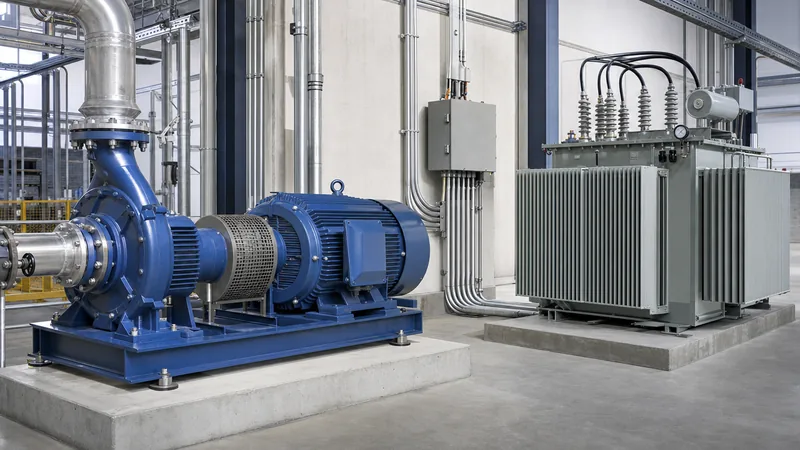
When feeding these motors from standard factory substations, engineers frequently coordinate their primary distribution using step-down transformers from an upstream unit substation designed for high-inertia motor starting.
Motor Starting Methods and System Inrush Impact
The starting method chosen for a three phase electric motor directly governs the locked-rotor apparent power (kVA) drawn from the supplying electrical distribution network. Direct-on-line (DOL) starting imposes the highest stress on the distribution infrastructure.
According to IEC 60034-12 Table 2 and NEMA MG 1 locked rotor code letters, starting across the line typically demands an inrush current of 6.0 to 8.2 times the full load current (FLC). This transient current operates at a low lagging power factor, frequently between 0.20 and 0.35. The heavy inductive pull causes an instantaneous voltage drop ($\%\Delta V$) across upstream cables, circuit breakers, and distribution transformers.
If the supply bus voltage drops by more than 15% during motor acceleration, critical facility risks emerge:
- Holding coils in adjacent electromagnetic contactors can drop out, de-energising running processes.
- Motor acceleration torque drops with the square of the terminal voltage ($T \propto V^2$), potentially stalling high-inertia loads such as centrifugal chillers or rock crushers.
- Thermal protection relays can trip prematurely due to extended acceleration times and elevated thermal $I^2t$ accumulation in the stator windings.
To mitigate inrush impact, facilities utilise soft starters, star-delta starters, or variable frequency drives (VFDs). However, VFDs introduce non-linear current harmonics that require harmonic-mitigating dry-type transformers or K-rated distribution units to manage winding eddy current heating.
Transformer Sizing for 3 Phase Electric Motors (Worked Calculation)
Properly sizing a dedicated distribution transformer for 3 phase electric motors requires evaluating both continuous thermal capacity and peak instantaneous motor-starting voltage dip. Neglecting starting transients is a frequent cause of nuisance tripping and transformer overheating.
Consider an industrial pump station requiring a dedicated oil-immersed transformer to feed a single 250 kW (335 hp), 400 V, 50 Hz, 4-pole three phase electric motor. The motor nameplate provides:
- Rated Power ($P$): 250 kW
- Operating Line Voltage ($V_L$): 400 V
- Full Load Efficiency ($\eta$): 95.8% (0.958, IE3 Premium Efficiency)
- Full Load Power Factor ($\cos\phi$): 0.88
- Starting Method: Direct-on-Line (DOL)
- Locked Rotor Current Ratio ($I_{start} / I_{FLC}$): 6.8
- Maximum permissible bus voltage drop: 10%
First, calculate the Full Load Amperes ($I_{FLC}$):
$$I_{FLC} = \frac{P}{\sqrt{3} \times V_L \times \cos\phi \times \eta} = \frac{250,000}{1.732 \times 400 \times 0.88 \times 0.958} = 428.1\text{ A}$$
Next, determine steady-state running apparent power ($S_{run}$):
$$S_{run} = \frac{P}{\eta \times \cos\phi} = \frac{250}{0.958 \times 0.88} = 296.5\text{ kVA}$$
Now evaluate starting apparent power ($S_{start}$), assuming an inrush power factor ($\cos\phi_{start}$) of 0.28:
$$I_{start} = 428.1\text{ A} \times 6.8 = 2,911\text{ A}$$
$$S_{start} = \sqrt{3} \times 400\text{ V} \times 2,911\text{ A} \times 10^{-3} = 2,016.8\text{ kVA}$$
To limit the transient voltage drop to $\Delta V \le 10\%$ on a transformer with an impedance ($Z_t$) of 5.5% (0.055 per unit), calculate the required transformer rating ($S_{xfmr}$):
$$\Delta V_{pu} \approx \frac{S_{start}}{S_{xfmr}} \times Z_t \times \sin\phi_{start}$$
Where $\sin\phi_{start} = \sqrt{1 - 0.28^2} = 0.96$. Re-arranging for minimum transformer rating to satisfy starting limits:
$$S_{xfmr} \ge \frac{S_{start} \times Z_t \times \sin\phi_{start}}{\Delta V_{allowable}} = \frac{2,016.8 \times 0.055 \times 0.96}{0.10} = 1,064.8\text{ kVA}$$
While steady-state thermal load only requires a 315 kVA unit, DOL motor starting constraints dictate specifying a standard 1,250 kVA transformer, or alternatively retrofitting a soft starter to allow using a 500 kVA or 630 kVA oil-immersed transformer.
Comparative Analysis: Starting Methods and Supply Sizing
Selecting the correct motor starting configuration directly impacts upstream distribution transformer kVA requirements, switchgear fault duty ratings, and capital expenditure.
The following table outlines how different starting methods alter starting current, starting torque, and the minimum transformer sizing multiplier relative to motor nominal rating:
| Starting Method | Starting Current (% of FLC) | Starting Torque (% of FLT) | Typical Starting Power Factor | Recommended Min Transformer Rating (Multiple of Motor kW) |
|---|---|---|---|---|
| Direct-On-Line (DOL) | 600% – 800% | 150% – 250% | 0.20 – 0.35 | 3.5x – 4.5x Motor kW |
| Star-Delta (Wye-Delta) | 200% – 260% | 30% – 50% | 0.30 – 0.45 | 1.8x – 2.2x Motor kW |
| Autotransformer (70% Tap) | 300% – 400% | 50% – 75% | 0.30 – 0.40 | 2.0x – 2.5x Motor kW |
| Electronic Soft Starter | 250% – 350% | 40% – 80% (Adjustable) | 0.40 – 0.55 | 1.5x – 1.8x Motor kW |
| Variable Frequency Drive (VFD) | 100% – 120% | 100% – 200% (Full Torque) | 0.95 – 0.98 | 1.25x – 1.35x Motor kW |
For installations in commercial buildings or facilities operating on secondary services, configuring the distribution system via a 208V 3 phase power board requires larger conductor cross-sections to mitigate $I^2R$ copper losses during sustained motor run cycles.
Best Practices for Motor Feeder and Transformer Selection
Specifying electrical supply gear for medium-to-large motor installations requires compliance with IEC 60076-1 and national wiring regulations such as BS 7671 or NFPA 70 (NEC Article 430).
Electrical project engineers should implement the following engineering practices during installation design:
- Impedance Coordination: Specify low-impedance transformers (e.g., 4.0% to 5.0% rather than 6.5% to 7.5%) when feeding large DOL motors to minimize voltage drop, provided downstream short-circuit interrupting ratings of circuit breakers remain compliant.
- Thermal Overload and Insulation Class: Select distribution transformers with Class H insulation or a 65°C oil temperature rise limit to withstand repetitive starting thermal shock cycles.
- Cable Sizing for Voltage Drop: Size feeder cables to limit full-load continuous steady-state drop to under 3%, and total starting transient drop at the motor terminals to under 12%, accounting for cable inductance. Review detailed engineering recommendations in our industrial power system installation guide.
- Harmonic De-rating: When feeding motors via six-pulse or twelve-pulse variable speed drives, specify drive-isolation transformers with electrostatic shielding and an appropriate K-factor (K-4 to K-13) to prevent localized eddy heating in the transformer core and windings.
Next steps: specifying and sourcing
When preparing technical tender documents or requests for quotation (RFQs) for industrial motor supply systems, include motor full load current, starting method, duty cycle (S1 through S8), and maximum allowable bus voltage dip. Matching these motor parameters with a suitable distribution transformer guarantees reliable plant commissioning without disruptive voltage dips. Explore our engineered range of liquid-filled and cast-resin units on the products overview page, or submit your single-line diagrams, motor load schedules, and ambient site conditions directly through our transformer quotation page or engineering contact page for tailored technical support.
Frequently asked questions
what is a 3 phase motor
A 3 phase motor is an electromechanical machine powered by three alternating currents of equal frequency and displaced by 120 degrees. This creates a rotating magnetic field that turns the rotor without needing capacitors or auxiliary windings. It provides higher efficiency, torque consistency, and operational lifespan than single-phase motors.
Can a three phase electric motor run on single phase power?
A three phase electric motor cannot run directly on single-phase power without modification. It requires a phase converter, an engineered capacitor bank (static converter), or a variable frequency drive (VFD) that accepts single-phase AC input and synthesizes a three-phase pulse-width-modulated (PWM) output.
What happens if a 3 phase electric motor loses one phase?
If a 3 phase electric motor loses one supply phase while operating, it enters a dangerous condition known as single-phasing. The motor will draw excessive current through the remaining two phases, causing rapid winding overheating, severe vibration, and eventual insulation burnout unless isolated by phase-failure relays.
Why do three phase motors have higher efficiency than single phase motors?
Three phase motors have higher efficiency because they produce a uniform, constant electromagnetic torque rather than the pulsating torque inherent in single-phase machines. The continuous rotating magnetic field eliminates auxiliary starting switches and split-phase windings, reducing stator copper losses and mechanical vibration.
How does motor starting current affect the upstream distribution transformer?
Motor starting current draws 6 to 8 times nominal full-load current at a low power factor during direct-on-line starts. This causes an instantaneous reactive voltage drop across the transformer leakage reactance, which can trigger undervoltage relays or drop out sensitive control gear if the transformer kVA is undersized.
Tags: three phase electric motor what is a 3 phase motor 3 phase electric motors motor three phase 3 ph motor


