Key takeaways
- Transformer accessories provide essential protective monitoring, environmental isolation, and thermal control to preserve core and winding integrity.
- Standard protective fittings defined in IEC 60076-22 and IEEE C57.148 include Buchholz relays, sudden pressure relays, magnetic oil gauges, and pressure relief valves.
- Bushing technology dictates high-voltage clearance and operational reliability, transitioning rapidly from oil-impregnated paper (OIP) to resin-impregnated synthetic (RIS) designs.
- Cooling hardware such as fans, radiator banks, and oil pumps determines dual MVA ratings across ONAN, ONAF, and OFAF operational regimes.
- Maintaining an audited inventory of critical transformer spare parts—especially nitrile gaskets, silica gel desiccant, and backup monitoring sensors—prevents catastrophic outage extensions.
Quick answer: Transformer accessories are auxiliary mechanical and electrical subsystems mounted externally or internally on a transformer to provide protection, thermal management, dielectric containment, and operational monitoring. Governed by international standards such as IEC 60076-22 and IEEE C57.148, these fittings safeguard the active core-and-coil assembly against electrical faults, overheating, environmental contamination, and structural overpressure.
While the magnetic core and copper or aluminium windings constitute the operational heart of any power apparatus, a unit cannot operate reliably without high-grade transformer accessories. In transmission networks and industrial distribution plants, auxiliary components transform a passive electromagnetic frame into an active, monitored asset. Whether managing fluid expansion in mineral oil or facilitating high-voltage network interconnections, selecting the correct accessory fittings directly dictates plant uptime and asset service life. Complementing the base tank architecture detailed in our guide to transformers internal components, this technical guide examines the functional categories, engineering parameters, and replacement protocols for primary transformer auxiliary fittings.
Protective Transformer Accessories for Fluid and Gas Monitoring
Protective transformer accessories detect nascent electrical faults and physical anomalies within fluid-immersed tanks prior to catastrophic failure. Foremost among these is the double-float Buchholz relay, installed in the inclined pipework between the main tank and the conservator vessel. Under IEC 60076-22-1, the Buchholz relay responds to both slow gas accumulation (generating an alarm via an upper reed switch triggered by 100 to 250 cm³ of accumulated gas) and sudden oil surges (triggering an instantaneous trip circuit when liquid velocities exceed 0.70 to 1.50 m/s). This mechanism provides early detection of inter-turn short circuits, core insulation breakdown, and dielectric breakdown.
For hermetically sealed transformers or large autotransformers operating on power grids, mechanical overpressure protection is provided by spring-loaded Pressure Relief Devices (PRD) and Sudden Pressure Relays (SPR). A PRD features a visual directional pin and microswitches rated up to 10 A at 250 V AC to trip the primary circuit breaker within 2 milliseconds if internal tank pressure breaches calibrated limits (typically 35 to 70 kPa). Similarly, magnetic liquid level gauges (MOG) provide continuous indication of fluid volume across thermal expansion cycles, incorporating low-level trip switches to protect against catastrophic dielectric loss, as detailed in our guide to transformer protection systems.
High-Voltage Bushings and Terminal Accessories
Bushing assemblies act as insulated terminal feedthroughs that conduct rated load and fault currents from the internal windings through the grounded steel tank. Modern substations deploy high-voltage bushings compliant with IEC 60137 and IEEE C57.19.00, rated for system voltages spanning 11 kV to 765 kV with basic impulse insulation levels (BIL) exceeding 1,050 kV. While older installations relied on Oil-Impregnated Paper (OIP) cores housed in porcelain envelopes, modern specifications mandate Resin-Impregnated Paper (RIP) or Resin-Impregnated Synthetic (RIS) bushings with silicone composite insulators. These dry-type capacitive grading cores eliminate explosion hazards, resist severe seismic activity, and demonstrate hydrophobic surface performance under heavy atmospheric pollution.
Terminal accessories also incorporate embedded bushing Current Transformers (BCTs) housed within the mounting turrets. BCTs provide critical metering and relay signals (such as 5P20 or 0.2S accuracy classes) for differential and overcurrent protection schemes. Additionally, spark gaps or arcing horns are calibrated across specific air gap distances to divert lightning-induced line surges away from the bushing shed profiles, reinforcing the surge arresters positioned at the substation gantry.
Cooling System Accessories and Forced Circulation Hardware
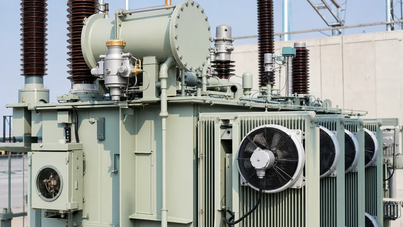
Cooling accessories regulate the thermal equilibrium of the transformer by transferring core and copper losses from the tank fluid to the ambient atmosphere. The cooling apparatus transitions an asset from natural oil, natural air (ONAN) convective cooling to forced air (ONAF) or forced oil and air (OFAF) configurations, commonly increasing operational throughput capacity by 25% to 66%. Radiator banks constructed from 1.2 mm to 1.5 mm cold-rolled steel panels are welded or bolted via flanged isolation butterfly valves directly to the tank walls, permitting individual radiator maintenance without draining the main bulk fluid.
Aerodynamic axial fans equipped with galvanised wire guards, IP55-rated squirrel-cage induction motors, and composite impellers provide forced airflow across radiator surfaces. For heavy transmission units, glandless centrifugal oil pumps circulating up to 120 m³/h are installed in the bottom headers. These pumps integrate mechanical paddle-type flow indicators with dual alarm contacts to warn control systems of stalled circulation, directly preventing hotspot temperatures from violating IEC 60076-2 insulation limits during peak load events.
Temperature and Environmental Control Fittings
Temperature indicators and desiccant breathers prevent thermal degradation of winding cellulose and block moisture ingress from the atmosphere. Dial-type Oil Temperature Indicators (OTI) and Winding Temperature Indicators (WTI) employ liquid expansion capillary systems connected to sensing bulbs positioned within the hottest top-oil layer. The WTI simulates true winding copper hotspots by routing secondary current from an internal BCT through an embedded heating element inside the instrument housing, outputting accurate thermal tracking with multiple microswitch setpoints for staged fan control, pump start, high-temperature alarm (e.g., 90 °C), and breaker trip (e.g., 105 °C).
Dehydrating breathers manage air intake as the fluid expands and contracts under variable loading, maintaining the high breakdown voltage necessary for operational reliability, as addressed in our guide to transformer oil purification. Air passes through a particulate oil bath before travelling across a bed of indicating silica gel desiccant. Advanced digital breathers replace manual silica replacement by incorporating solid-state heating elements, relative humidity sensors, and automated regeneration cycles that drive absorbed moisture out during the transformer's warm exhaust cycle.
Summary Specification of Vital Transformer Accessories
Standardising technical specifications for auxiliary components ensures interchangeable maintenance and predictable operation across heterogeneous transformer fleets.
| Accessory Name | Primary Function | Relevant Standard | Key Engineering Parameter | Maintenance Interval |
|---|---|---|---|---|
| Buchholz Relay | Nascent gas and oil surge detection | IEC 60076-22-1 | Gas volume: 100–250 cm³; Trip velocity: 0.7–1.5 m/s | 6 to 12 Months |
| Pressure Relief Device (PRD) | Instantaneous overpressure venting | IEEE C57.148 | Operating pressure: 35–70 kPa (±10%); Trip delay: < 2 ms | Annual visual / 3-yr trip test |
| Capacitance Graded Bushings | HV conductor isolation | IEC 60137 | Insulation: RIP / RIS; Tan delta (power factor): < 0.5% | Annual tan delta / capacitance test |
| Dehydrating Breather | Moisture extraction from intake air | DIN 42562 / IEC | Moisture adsorption capacity: > 20% by weight; Silica mass: 1–10 kg | Monthly visual / automated |
| WTI / OTI Instruments | Hotspot and bulk thermal measurement | IEC 60076-2 | Capillary length: up to 10 m; Accuracy: Class 1.5; 4 microswitches | Annual calibration check |
| On-Load Tap Changer (OLTC) | Dynamic ratio voltage regulation | IEC 60214-1 | Step voltage: 1.0–2.5%; Switching capacity: up to 1,500 A | 50,000 to 300,000 operations |
Essential Transformer Spare Parts and Inventory Strategy
Strategic warehousing of transformer spare parts prevents minor component failures from turning into extended substation outages. Power grid operators and industrial plants must classify spare components according to failure probability, lead times, and operational criticality. Long-lead items such as high-voltage RIP bushings, motor drive units for On-Load Tap Changers (OLTC), and specialised radiator modules often require 16 to 36 weeks for factory manufacture, factory acceptance testing, and delivery. Consequently, maintaining strategic on-site stock is mandatory for critical infrastructure tied into grid substations described in our transmission transformer guide.
Consumables and high-turnover spares must also be rigorously managed. These items include Nitrile Butadiene Rubber (NBR) and fluoropolymer (FKM) O-rings and flanged gaskets, which degrade under exposure to hot oil and ultraviolet radiation. Stored transformer spare parts must be housed in environmentally controlled storage facilities; rubber compounds require cool, dark storage below 25 °C without exposure to ozone, while spare RIP bushings must be stored vertically or equipped with nitrogen-pressurised transport hoods to eliminate ambient moisture ingress across their capacitive cores.
Inspection and Commissioning Procedure for Transformer Accessories
Commissioning transformer accessories requires systematic mechanical and electrical verification prior to energising the primary core and coils. Field engineers should follow this sequenced procedure during pre-commissioning:
- Mechanical Alignment and Gasket Inspection: Verify the physical mounting, verticality, and torque tolerances on all flange connections, including radiator butterfly valves, conservator pipework, and bushing turrets, confirming that elastomer gaskets exhibit nominal 25% to 30% compression without pinch shearing.
- Secondary Circuit Insulation Testing: Perform a 1,000 V DC insulation resistance test across all auxiliary wiring, terminal blocks, motor drive circuits, and internal microswitch contacts, confirming resistance values exceed 10 MΩ to ground.
- Buchholz Relay Pneumatic and Electrical Injection: Manually actuate alarm and trip reed contacts via the mechanical test petcock, then inject dry air using an automated test kit to confirm calibrated gas volume accumulation and the functioning of the upper alarm circuit.
- Thermal Instrument Calibration: Place OTI and WTI sensor bulbs into a stirred water bath with a calibrated reference thermometer, verifying dial tracking, switch actuation thresholds (fan bank 1, fan bank 2, alarm, trip), and 4–20 mA current loop transducer telemetry back to the SCADA system.
- PRD Contact Functional Verification: Manually trigger the auxiliary microswitch mechanical pull-ring on the pressure relief valve, confirming that primary breaker tripping lockouts actuate instantly and clear indicator flags present visible local indication.
- Dehydrating Breather Commissioning: Check that the oil trap level in the breather cup is charged to the fill line with clean dielectric oil, the transport shipping seal is fully removed from the air inlet, and silica desiccant exhibits active cobalt-free blue or orange coloration.
Next steps: specifying and sourcing
Specifying the proper accessories during transformer procurement requires complete integration between physical tank dimensions, environmental site conditions, and digital protection interfaces. When preparing tenders or replacement schedules, submit your Single Line Diagrams (SLD), ambient temperature extremes, seismic acceleration ratings, and communication protocol requirements (such as IEC 61850 or Modbus). Explore our heavy-duty power transformer solutions and factory-integrated oil-immersed transformers to view standardised, field-proven accessory configurations. To request complete technical datasheets or receive an engineering bill of materials for custom auxiliary packages, contact our engineering sales department via our quote page.
Frequently asked questions
What is the difference between a Buchholz relay and a sudden pressure relay?
A Buchholz relay is installed on conservator-type transformers to detect both slow gas accumulation and fast fluid surges through the connecting pipe. A sudden pressure relay is mounted directly on the main tank wall or cover—often in sealed-tank transformers—to respond exclusively to the dynamic rate of pressure rise caused by internal electrical arcs.
Why are RIP bushings preferred over OIP bushings in modern transformers?
Resin-Impregnated Paper (RIP) bushings feature dry, solid insulation that eliminates the risk of dielectric oil leakage and explosive fire hazards associated with Oil-Impregnated Paper (OIP). RIP bushings also provide superior thermal endurance, higher seismic resilience, and allow for flexible horizontal or angled installation angles.
How often should silica gel be replaced in a transformer breather?
Silica gel should be replaced or regenerated when two-thirds of the desiccant volume shifts from its active colour to its saturated colour, typically blue to pink or orange to green. Depending on local atmospheric humidity and load cycling, this generally occurs every 3 to 12 months for standard breathers.
What critical transformer spare parts should always be kept on-site?
Critical on-site transformer spare parts include complete sets of tank and bushing gaskets, one spare high-voltage and low-voltage bushing, replacement desiccant charges, spare auxiliary cooling fans, and complete trip microswitches for temperature indicators and pressure relief valves.
What standard governs power transformer accessories and fittings?
In international markets, transformer accessories are primarily governed by the IEC 60076-22 series covering power transformer and reactor fittings. In North American and IEEE-aligned jurisdictions, component engineering specifications are dictated by IEEE C57.148.
Tags: transformer accessories transformer spare parts power transformer fittings buchholz relay transformer bushings


