Key takeaways
- The core construction of transformer units uses cold-rolled grain-oriented (CRGO) silicon steel laminations between 0.23 mm and 0.30 mm thick to limit eddy currents and hysteresis loss.
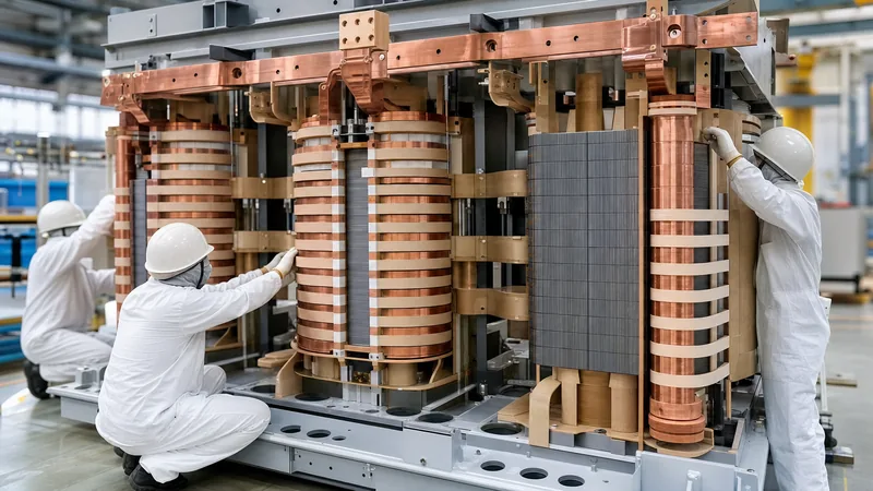
- Transformer windings are typically wrapped around structural insulating cylinders placed concentrically over the laminated magnetic core limbs.
- Low-voltage windings are installed directly adjacent to the grounded core limb to reduce the dielectric barrier thickness and ground clearance requirements.
- Dielectric insulation systems rely on Kraft paper and pressboard impregnated with mineral oil in liquid-filled units, or epoxy resin casting in dry-type transformers.
- Mechanical enclosures are constructed from structural steel with integrated radiators or corrugated cooling fins designed to withstand internal vacuum and overpressure conditions according to IEC 60076-1.
Quick answer: The construction of transformer units consists of three primary elements: a high-permeability magnetic core built from laminated electrical steel, conductive copper or aluminium windings arranged concentrically around the core limbs, and a dielectric insulation system. These internal assemblies are secured within an oil-filled steel tank or dry-type ventilated enclosure equipped with external bushings, cooling circuits, and tap changers.
Transformers serve as the mechanical and electromagnetic backbone of modern electrical distribution grids and industrial facilities. Whether designed for low-voltage secondary feeds or 110 kV primary substation interfaces, physical construction dictates short-circuit withstand capability, thermal efficiency, acoustic sound levels, and operational life expectancy. Selecting the right equipment requires a thorough understanding of how the core, conductive coils, structural clamping, and dielectric media interact under continuous electrical and mechanical stress.
Core Architecture and Magnetic Circuit Design
The magnetic core provides a continuous, low-reluctance path for mutual magnetic flux linking the primary and secondary electrical circuits. In modern industrial equipment, cores are constructed from high-grade, cold-rolled grain-oriented (CRGO) silicon steel sheets typically ranging from 0.23 mm to 0.30 mm in thickness. As detailed in our comprehensive transformer core engineering guide, laminating the magnetic steel significantly suppresses circular eddy current paths that would otherwise generate excessive internal heat and no-load losses.
Each lamination is coated with an inorganic chemical surface insulation layer (C-5 class) approximately 1 to 2 micrometres thick. The steel sheets are precision-cut and stacked in stepped cylindrical cross-sections to approximate a circle, providing structural support for circular coils while maximising the active iron area. Modern construction utilises step-lap mitered joints at 45-degree angles between the horizontal yokes and vertical limbs. This step-lap arrangement drastically reduces localized flux crowding and air-gap reluctance, decreasing no-load excitation current and trimming operational acoustic noise by 3 to 5 dB(A) compared to traditional butt-and-lap stacking.
What Are Transformer Windings Typically Wrapped Around?
What are transformer windings typically wrapped around during fabrication? Transformer windings are typically wrapped around rigid, high-density insulating cylinders fitted directly over the vertical laminated core limbs (also known as the core legs).
These insulating cylinders, manufactured from pressboard, phenolic-bonded paper, or resin-impregnated fibreglass, serve as both a mechanical winding mandrel and a primary dielectric barrier against the grounded steel core. Coils are almost never wound directly onto the metallic steel laminations due to ground insulation clearances and mechanical abrasion risks. Instead, coil construction follows a precise physical layering sequence:
- The grounded, stepped-cylinder CRGO core limb is mechanically clamped with non-magnetic steel bands or resin-glass tape.
- An insulating former tube (cylinder) made of high-grade electrical pressboard is positioned over the core limb, establishing an axial oil or air cooling duct.
- The low-voltage (LV) winding is wound over this inner cylinder. Placing the LV winding closest to the core minimizes the physical thickness of the insulation barrier needed between the conductor and the grounded core frame.
- A heavy inter-winding insulation barrier, consisting of solid pressboard cylinders and oil-guiding collars, is slipped over the outside of the LV coil.
- The high-voltage (HV) winding is wound over the outer insulating barrier, maximising radial physical separation from the grounded core limb.
Winding Types and Conductor Materials
Transformer windings convert electrical power between voltage levels through electromagnetic induction and must withstand severe radial and axial forces during through-fault short circuits. Conductors are manufactured from high-conductivity, oxygen-free copper (conductivity ≥ 100% IACS) or electrical-grade aluminium (EC 1350, conductivity ≥ 61% IACS). While copper offers superior mechanical yield strength and lower volumetric displacement, aluminium provides an economical alternative where physical enclosure footprint and weight constraints are less restrictive.
The physical geometry of the winding depends on current rating, voltage class, and Basic Impulse Insulation Level (BIL) requirements:
- Helical and Spiral Windings: Commonly used for low-voltage, high-current applications. Rectangular conductors or continuously transposed cable (CTC) are wound in continuous axial spirals, incorporating radial spacers to form unimpeded cooling channels.
- Continuous Disc Windings: Preferred for medium- and high-voltage applications above 15 kV. Flat conductors wrapped in thermally upgraded Kraft paper are wound into discrete radial discs separated by pressboard spacers, allowing superior withstand capability against transient switching impulses and lightning surges.
- Foil Windings: Often used in the low-voltage sections of dry-type transformer units. Broad copper or aluminium sheets span the entire axial height of the coil, virtually eliminating axial mechanical stress components during external short circuits.
Solid and Liquid Insulation Systems
The insulation system must isolate phase-to-phase, phase-to-ground, and turn-to-turn potentials while facilitating efficient heat transfer away from internal conductors. Solid insulation consists of cellulose-based Kraft paper, pressboard boards, corrugated spacing sticks, and creepage blocks. In high-temperature dry-type units, inorganic materials such as aromatic polyamide paper (Nomex) and Class H (180°C) or Class C (220°C) cast epoxy resins replace standard cellulose.
In fluid-immersed systems, highly refined uninhibited or inhibited naphthenic mineral oil (meeting IEC 60296 or ASTM D3487) fills every internal void. The fluid serves as both a primary dielectric medium—with a breakdown strength typically exceeding 50 kV across a standard 2.5 mm test gap—and a convection cooling agent. For sensitive installations demanding fire-safety resilience or environmental biodegradability, natural or synthetic ester liquids are substituted. Comprehensive details on fluid selection and condition monitoring can be found in our oil-filled transformer engineering guide.
Core-Type vs. Shell-Type Structural Comparison
The mechanical layout of a transformer falls into one of two fundamental geometries: core-type or shell-type construction. In core-type designs, the windings encircle the laminated vertical limbs of the magnetic core. In shell-type designs, the laminated steel core surrounds and encloses the stationary windings on both outer flanks.
The operational and manufacturing distinctions between these two construction methods are summarized in the engineering comparison below:
| Construction Feature | Core-Type Construction | Shell-Type Construction | Engineering Impact |
|---|---|---|---|
| Winding Placement | Concentric coils wrapped around core limbs | Interleaved pancake coils surrounded by iron | Core-type simplifies HV radial insulation clearances |
| Magnetic Path | Single path per phase, two vertical limbs | Divided flux paths across multiple outer yokes | Shell-type allows reduced core limb cross-section |
| Mechanical Withstand | High radial hoop strength with circular coils | Superior bracing against axial short-circuit forces | Core-type is easier to clamp for standard distribution |
| Cooling Performance | Excellent oil/air duct routing along limbs | Requires complex internal coolant baffle paths | Core-type provides accessible convective flow |
| Repair & Maintenance | Straightforward coil dismantling and inspection | Difficult disassembly requiring lamination unstacking | Core-type reduces factory and field overhaul time |
| Dominant Application | Global distribution and medium-power grids | Extra-high voltage (EHV) and heavy industrial furnaces | Determines capital cost and weight distribution |
Tank Fabrication, Cooling Circuits, and Bushings
The external tank houses the active core-and-coil assembly, providing mechanical protection, fluid containment, and physical support for operational accessories. Fabricated from structural mild steel plate (typically 5 mm to 10 mm wall thickness), tanks are reinforced with internal and external stiffeners to withstand full vacuum during oil filling operations and internal operating pressures specified by IEEE C57.12.00.
Heat generated by active core and winding losses must be continuously rejected into the environment. Tanks utilize corrugated cooling walls for distribution ratings below 2,500 kVA, or external bolt-on radiator banks equipped with auxiliary cooling fans for forced-air (ONAF or OFAF) thermal regimes. Electrical connections penetrate the sealed tank wall through porcelain, epoxy resin, or oil-impregnated paper (OIP) bushings. In three-phase utility deployments, these structures are integrated with off-circuit tap changers (OCTC) or on-load tap changers (OLTC) to adjust winding turn ratios under varying system loads, as outlined in our 3-phase transformer guide.
Next steps: specifying and sourcing
When specifying equipment for utility, commercial, or industrial applications, providing complete site data ensures your equipment meets exact thermal and electromagnetic requirements. Prepare your single-line diagrams, rated capacity (kVA or MVA), primary and secondary voltages, connection vector group (such as Dyn11), Basic Impulse Insulation Level (BIL), impedance percentage (%Z), and environmental site ambient conditions. Explore our heavy-duty power transformers, fluid-filled oil-immersed transformers, and flame-retardant dry-type transformers designed to IEC and IEEE standards. Submit your project requirements through our direct quote request form or reach out to our engineering support specialists on the contact page for tailored technical consultation.
Frequently asked questions
what are transformer windings typically wrapped around
Transformer windings are typically wrapped around rigid, high-density insulating cylinders placed over the laminated vertical core limbs. This structural cylinder provides electrical isolation from the grounded steel while maintaining precise radial cooling ducts for oil or air circulation.
What is the primary material used in transformer core construction?
Transformer cores are constructed from cold-rolled grain-oriented (CRGO) silicon steel laminations coated with an inorganic insulating film. The silicon addition increases electrical resistivity, reducing circular eddy current losses and minimising magnetic hysteresis.
Why is the low-voltage winding placed closer to the core than the high-voltage winding?
The low-voltage winding is placed adjacent to the core because it requires less dielectric insulation barrier thickness to ground. Placing the high-voltage winding on the outside reduces the total volume of insulating material needed, simplifying construction and lowering costs.
What is the difference between core-type and shell-type transformer construction?
In core-type construction, the conductive windings encircle the outer vertical limbs of the magnetic core. In shell-type construction, the magnetic iron core surrounds and encloses the internal windings, providing enhanced mechanical bracing for severe industrial loads.
What role does insulation oil play in transformer construction?
Insulation oil serves two vital roles: dielectric insulation and thermal cooling. It fills internal micro-voids in the solid cellulose paper to prevent electrical partial discharges and circulates through the windings to transfer heat to the external tank radiators.
Tags: construction of transformer transformer core transformer windings transformer insulation power transformer


