Key takeaways
- A wind turbine transformer steps up generator output voltage (typically 690 V to 1,140 V) to medium-voltage collector levels between 11 kV and 36 kV.
- Transformers in wind power applications must comply with IEC 60076-16, which governs design requirements for wind turbine step-up duty under extreme thermal cycling.
- Harmonic currents from full-rated converter topologies generate eddy-current winding losses requiring a calculated transformer harmonic factor (K-factor) derating.
- Installation location inside the nacelle, tower base, or an external pad-mounted enclosure dictates fire safety ratings, cooling configuration, and maximum dimensions.
- Factory testing protocols must include lightning impulse tests per IEC 60076-3 and partial discharge evaluation under cyclic thermal stress.
Quick answer: A wind turbine transformer is a specialised step-up unit that converts low-voltage generation output (typically 690 V or 1,140 V) up to medium-voltage collector network levels (11 kV to 36 kV) within or adjacent to a turbine structure. Engineered under IEC 60076-16, it withstands cyclic mechanical vibration, rapid thermal swings, transient switching overvoltages, and non-sinusoidal harmonic loading from power electronic converters.
Integrating multi-megawatt modern turbines into local and regional grids demands robust mechanical and electrical design margins. Unlike base-load industrial units operating under steady loads, wind power transformers face violent load swings caused by fluctuating wind speeds, frequent no-load energisations, and intense harmonic profiles produced by pulse-width modulation (PWM) power converters. Selecting the correct insulation class, cooling medium, core geometry, and enclosure footprint directly impacts turbine levelised cost of energy (LCOE) and prevents catastrophic dielectric breakdown. For complete network synchronisation insights, review our guide to grid integration of renewable energy sources.
Operating Duties and Stresses on a Wind Turbine Transformer
Operating duties for wind power transformers deviate substantially from conventional grid distribution units due to severe environmental and electrical stress profiles. A typical wind turbine step-up unit undergoes hundreds of thermal expansion and contraction cycles annually as wind velocities ramp from cut-in speeds (roughly 3 m/s) to rated generation (11 to 14 m/s) and back to cut-out conditions.
These operational conditions introduce three primary degradation mechanisms defined in IEC 60076-16 clause 5.2:
- Thermal cycling and mechanical fatigue: Intermittent loading induces cyclic expansion in copper conductors, core laminations, and structural tie plates. Over time, differential thermal expansion between conductors and solid insulation leads to structural slackening, micro-fissuring, and decreased clamping force across the winding blocks.
- High-frequency switching transients: Vacuum circuit breakers (VCB) within the turbine switchgear create high-frequency restrikes and steep-fronted transient overvoltages (with dV/dt exceeding 100 kV/μs). These reflections cause non-uniform dielectric stress across the first turns of the medium-voltage winding, demanding reinforced inter-turn insulation and electrostatic shields.
- Severe harmonic spectrums: Variable-speed turbines utilising Type 3 (doubly-fed induction generators) or Type 4 (full-power back-to-back converters) inject significant harmonic currents into the low-voltage windings. These harmonics, ranging from the 5th up to the 50th order, increase stray eddy current losses, accelerating hot-spot temperatures as examined in our transformer winding temperature guide.
- Structural vibration and g-forces: Units mounted in the nacelle experience continuous low-frequency structural swaying (0.2 Hz to 2 Hz) combined with drive-train vibrations (10 Hz to 60 Hz). Factory bracing must maintain core and coil integrity under acceleration levels up to 0.5g horizontally and 1.0g vertically.
Location Architectures: Nacelle, Tower Base, and Onshore Transformers
The choice of physical transformer placement determines structural balance, fire protection architectures, cabling capital costs, and ease of routine maintenance. Modern wind farm designs deploy three distinct physical configurations, each presenting unique engineering trade-offs.
For nacelle-mounted configurations, designers place compact dry-type or synthetic ester units directly behind the generator. While this topology eliminates expensive low-voltage high-current busbars running down the tower, it concentrates mass at high elevations, requiring heavier tower structures and complex crane operations for replacement. Dry-type cast resin units or high-flashpoint fluid units are mandatory in this space to satisfy fire safety protocols.
Tower-base installations locate the step-up transformer within the lowest internal platform of the steel or concrete tower section. This approach keeps equipment sheltered from marine or desert ambient conditions while simplifying service access. However, internal clearances are tightly constrained by the tower diameter, demanding custom narrow-footprint designs with high-efficiency cooling air ducts or external heat exchangers.
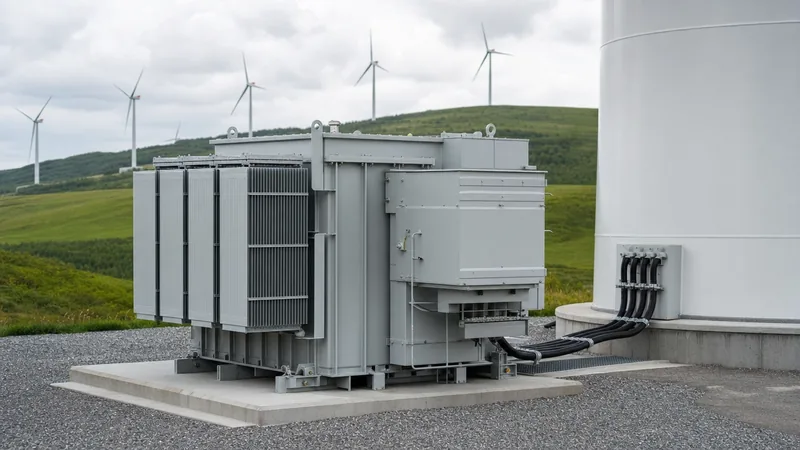
External configurations rely on onshore transformers installed adjacent to the turbine foundation in outdoor pad-mounted enclosures. Utilizing a standalone pad-mounted transformer or modular prefabricated transformer substation lowers crane costs and isolates fire hazards completely from the structural tower. These units connect to the nacelle via bundled low-voltage flexible cables and feed directly into the underground medium-voltage collector loop. For detailed enclosure layouts, reference our unit substation engineering guide.
Dielectric Mediums: Dry-Type vs Liquid-Immersed Transformers
Selecting between dry-type cast resin and liquid-immersed dielectric systems depends on fire safety mandates, environmental risk assessments, and dimensional envelopes. Both technologies occupy distinct operational niches within utility-scale wind power generation.
The engineering attributes of both systems compare as follows:
| Engineering Parameter | Cast Resin Dry-Type (F or H Class) | Synthetic Ester Immersed (K-Class) | Mineral Oil Immersed (O-Class) |
|---|---|---|---|
| Standard Compliance | IEC 60076-11 | IEC 60076-14 / IEC 60076-16 | IEC 60076-2 / IEEE C57.12.00 |
| Fire Point / Class | Non-flammable (F1 per IEC 60076-11) | >300 °C (K3 Class) | ~165 °C (O1 Class) |
| Typical Locations | Nacelle, Tower Base | Nacelle, Tower Base, Padmount | External Padmount Only |
| Footprint & Mass Ratio | 1.25x (Heavier / Larger) | 1.0x (Baseline Compact) | 1.05x (Baseline Standard) |
| Thermal Time Constant | Short (Rapid temperature rise) | Long (High thermal inertia) | Long (High thermal inertia) |
| Environmental Hazard | Zero leak potential | Readily biodegradable (OECD 301) | Persistent, high water hazard |
| Cooling Configuration | AN / AF (Forced air blowers) | KNAN / KNAF / KDWF | ONAN / ONAF |
Dry-type units eliminate all fluid contamination risks, making them the preferred technology for sensitive drinking water catchments. Conversely, synthetic ester liquid-immersed units allow smaller overall outer dimensions due to superior dielectric clearance margins. They also feature high fire points exceeding 300 °C, enabling safe installation inside towers while retaining high thermal time constants that absorb short-term wind gust overloads without excessive winding insulation degradation. Where fire containment systems are engineered for external units, consult our guide on transformer fire protection system designs.
Harmonic Spectrum Analysis and K-Factor Sizing Calculation
Harmonic currents generated by wind turbine power converters create supplementary winding losses that require precise derating calculations to prevent exceeding insulation thermal limits. Converter switching produces non-sinusoidal currents rich in odd harmonics that substantially increase winding eddy-current losses ($P_{EC}$) and stray load losses ($P_{OSL}$).
According to IEEE C57.110 and IEC 60076-16 Annex A, the total load loss under non-sinusoidal conditions is calculated using the harmonic loss factor ($F_{HL}$), also designated as K-factor in North American practice. Let us review a worked engineering calculation for a 3.45 MVA, 690 V / 33 kV step-up transformer connected to a full-scale voltage source converter.
Step 1: Input Parameters and Harmonic Current Spectrum
- Rated apparent power ($S_n$): 3,450 kVA
- Rated low-voltage line current ($I_1$): 2,886 A at 690 V
- Fundamental eddy-current loss ratio ($P_{EC-R}$): 12% of total full-load ohmic resistance loss ($I^2R$)
- Measured or simulated converter harmonic current distribution:
- Fundamental (h = 1): 1.000 pu
- 5th harmonic (h = 5): 0.045 pu
- 7th harmonic (h = 7): 0.030 pu
- 11th harmonic (h = 11): 0.018 pu
- 13th harmonic (h = 13): 0.012 pu
- High-frequency PWM ripple around 2.5 kHz (h = 50): 0.008 pu
Step 2: Harmonic Loss Factor Calculation Formula
The harmonic loss factor for winding eddy currents ($F_{HL}$) is expressed as:
$$F_{HL} = \frac{\sum_{h=1}^{h_{max}} \left(\frac{I_h}{I_1}\right)^2 \cdot h^2}{\sum_{h=1}^{h_{max}} \left(\frac{I_h}{I_1}\right)^2}$$
Summing the squared harmonic components multiplied by their harmonic order squared:
- Fundamental: $(1.000)^2 \times 1^2 = 1.000$
- 5th Harmonic: $(0.045)^2 \times 5^2 = 0.002025 \times 25 = 0.0506$
- 7th Harmonic: $(0.030)^2 \times 7^2 = 0.0009 \times 49 = 0.0441$
- 11th Harmonic: $(0.018)^2 \times 11^2 = 0.000324 \times 121 = 0.0392$
- 13th Harmonic: $(0.012)^2 \times 13^2 = 0.000144 \times 169 = 0.0243$
- 50th Harmonic: $(0.008)^2 \times 50^2 = 0.000064 \times 2500 = 0.1600$
Numerator total: $1.000 + 0.0506 + 0.0441 + 0.0392 + 0.0243 + 0.1600 = 1.3182$
Denominator total (total root-sum-square current pu): $\sum (I_h/I_1)^2 = 1.000 + 0.002025 + 0.0009 + 0.000324 + 0.000144 + 0.000064 = 1.00346$
$$F_{HL} = \frac{1.3182}{1.00346} = 1.3137$$
Step 3: Derating and Nameplate Specification
The winding eddy losses under rated load increase by 31.37%. To ensure the hottest-spot temperature rise does not exceed the 65 K limit (for mineral oil) or 110 K limit (for Class H dry-type resin), the maximum continuous converter rating must not exceed:
$$I_{max} = I_R \times \sqrt{\frac{1 + P_{EC-R}}{1 + F_{HL} \cdot P_{EC-R}}} = I_R \times \sqrt{\frac{1 + 0.12}{1 + (1.3137 \times 0.12)}} = I_R \times \sqrt{\frac{1.12}{1.1576}} = 0.9836 \text{ pu}$$
Consequently, the design engineer must specify a standard baseline unit rated at no less than $3,450 / 0.9836 = 3,507\text{ kVA}$, or specify a custom winding wound with Continuously Transposed Conductor (CTC) to suppress fundamental eddy losses down to below 7%. For broader network sizing methods, use our kVA sizing calculator and guide.
Protection Against Resonant Overvoltages and Switching Transients
Switching transients from vacuum circuit breakers coupled with cable capacitance generate severe high-frequency resonant overvoltages that damage wind farm transformer insulation. When a breaker operates to disconnect a turbine during no-load or low-load periods, arc re-ignitions generate high-frequency current interruptions. The resulting voltage escalation reflects back and forth along the medium-voltage inter-array cable array.
If the natural frequency of the collector cable matches an internal resonance frequency of the transformer high-voltage winding (commonly between 20 kHz and 300 kHz), internal voltage amplification factors of 3 to 6 times the crest system line-to-ground voltage can occur inside the winding body. Standard lightning arresters installed at transformer terminals do not protect against this internal winding resonance because terminal peak voltages often remain below the arrester protective sparkover or discharge threshold.
Engineers must implement three protective measures per IEC 60076-16 clause 7.3:
- Installation of Surge Arresters directly on terminals: Station-class metal-oxide varistors (MOV) with high energy absorption capacity (Class 2 or 3 per IEC 60994-4) must be fitted within shielded separable connectors directly on the bushing elbows.
- RC Snubber Circuits: Specifying dedicated resistance-capacitance (RC) snubber networks tuned to dampen high dV/dt transient waveforms. A typical snubber configuration incorporates a 20 to 50 ohm non-inductive resistor in series with a 0.1 to 0.25 microfarad high-voltage capacitor installed on each phase.
- Interleaved or Shielded High-Voltage Windings: Transformers must be wound with electrostatic shield rings between disc sections to achieve linear surge voltage distribution along the winding stack, preventing localized dielectric puncture across line-end discs.
Core and Coil Design: Vibration Withstand and Short-Circuit Integrity
Dynamic short-circuit withstand capabilities and rigid mechanical construction are mandatory requirements for reliable operation within wind turbine environments. Transformers must survive severe external grid faults alongside sustained structural vibration caused by wind gusts and mechanical blade passing frequencies.
Short circuits on collector circuits present severe thermal and mechanical stresses. In accordance with IEC 60076-5, a wind turbine step-up transformer must withstand dynamic short-circuit forces without physical displacement of conductors or core laminations. Radial electromagnetic forces tend to burst outer windings and crush inner windings, while axial forces displace winding coils in opposing directions, driving them against structural end-blocks.
To withstand these operational loads, manufacturers employ specific core and coil fabrication techniques:
- High-grade grain-oriented silicon steel (CRGO): Cores utilize laser-scribed, low-loss magnetic steel assembled with step-lap mitered joints. This suppresses no-load magnetising currents, curtails core vibration, and reduces acoustic emissions below 60 dB(A).
- Hydraulic winding pre-compression: Coiled assemblies undergo continuous axial pre-clamping using thick structural steel pressure plates and non-shrink densified laminated wood spacers. Clamping pressures are calibrated to exceed maximum anticipated electromagnetic fault forces by a factor of 1.25.
- Epoxy-bonded conductors: Low-voltage windings carrying high currents (exceeding 2,500 A) are wound with epoxy-bonded transposed conductors or complete foil-wound copper sheets. Thermal curing bonds adjacent conductors into an integrated rigid block with superior short-circuit withstand integrity.
- Resilient base isolators: Internal core-and-coil frames feature elastomeric or spring-type anti-vibration damping mounts rated for three-axis excitation, isolating internal active components from turbine tower resonant frequencies.
Factory Acceptance Testing and Commissioning Protocols
Factory Acceptance Testing (FAT) must rigorously confirm electrical performance, insulation integrity, and mechanical resilience under wind duty stresses before units ship to site. Routine tests must strictly follow IEC 60076-1 and IEC 60076-16 Table 4 requirements.
Engineers responsible for witnessing factory acceptance should follow this inspection sequence:
- Winding resistance and ratio verification: Verify balance across all tap positions using digital micro-ohmmeters. Ratio tolerances must remain within ±0.5% of specified values.
- No-load losses and excitation current: Measure core losses at 90%, 100%, and 110% of rated voltage. Elevated no-load current under overexcitation indicates core saturation risks during grid islanding.
- Impedance voltage and load loss: Measure short-circuit impedance at fundamental frequency; results must match nameplate values within ±7.5% per IEC tolerances to ensure accurate parallel operation along the collector string.
- Full-wave lightning impulse testing: Execute standard 1.2/50 μs lightning impulses accompanied by chopped-wave tests per IEC 60076-3. For a 33 kV collector voltage, basic insulation levels (BIL) should reach 170 kV or 200 kV crest.
- Partial discharge (PD) testing: Cast resin dry-type transformers must exhibit partial discharge levels strictly under 10 pC at 1.8 times rated line-to-ground voltage. Ester or oil-filled units must not exceed 100 pC during extended induced overvoltage cycles.
- Vibration and structural resonance scans: Nacelle-mounted models undergo multi-axis dynamic frequency response analysis to detect mechanical natural frequencies within 5 Hz to 50 Hz.
Explore standard procedures in our guide to power transformer testing and factory acceptance.
Engineering Specification Checklist for RFQs
A comprehensive Request for Quotation (RFQ) checklist prevents engineering oversights, expensive field retrofits, and delivery delays during wind farm procurement. When procuring wind power transformers, specifying engineers should provide the exact parameters outlined below.
| Category | Specification Requirement | Standard / Engineering Detail |
|---|---|---|
| Application Environment | Nacelle, Tower Base, or External Padmount | Identify enclosure IP/NEMA rating & ambient range (-25 °C to +50 °C) |
| Rated MVA & Voltages | Rated kVA, LV (e.g. 690 V), HV (e.g. 33 kV) | Vector group (commonly Dyn11 or Dyn5), neutral requirements |
| Converter Topology | Type 3 (DFIG) or Type 4 (Full Converter) | Include complete voltage and current harmonic spectrum through the 50th order |
| Applicable Standards | IEC 60076-16 / IEEE C57.12.01 / IEEE C57.12.00 | Wind turbine application specific amendments |
| Dielectric Medium | Dry-Type (Cast Resin) vs Fluid (Synthetic Ester / Oil) | Insulation class (Class F, H) or K-Class ester with >300 °C fire point |
| Transient Protection | Surge arresters and snubber circuit integration | BIL level (170 kV / 200 kV for 33 kV HV), provision for elbow MOVs |
| Impedance (%Z) | Standard: 6.0% to 8.5% | Tolerance band ±7.5% to restrict fault current and collector loop drops |
| Thermal Monitoring | PT100 RTDs in all phase windings and core | Integration to turbine SCADA via Modbus RS485 or fiber-optic outputs |
| Mechanical Acceleration | Seismic and structural dynamic limits | Continuous 0.5g lateral, 1.0g vertical dynamic acceleration withstand |
| Corrosion Class | External surface finish and hardware | ISO 12944 C5-M (Marine) or C4 (Industrial) coating systems |
Next steps: specifying and sourcing
Specifying the optimal wind turbine transformer requires balanced evaluation of installation envelope constraints, converter harmonic spectra, transient suppression schemes, and total cost of ownership. Whether your project involves repowering an existing onshore array or constructing a multi-megawatt greenfield installation, selecting the correct dielectric medium and short-circuit withstand capability is critical to long-term operational uptime.
Explore our engineering capabilities across medium-voltage power platforms, including utility-scale oil-immersed transformers, compact dry-type transformers, and high-capacity power transformers designed to support substation collector networks. When you are ready to review project drawings, confirm harmonic ratings, or request a complete quotation, reach out directly to our engineering team through our transformer quotation page or contact our technical office at our direct engineering contact portal.
Frequently asked questions
What is a wind turbine transformer?
A wind turbine transformer is an electrical step-up unit that converts the low voltage output generated by a turbine (typically 690 V or 1,140 V) to the wind farm medium-voltage collector system (11 kV to 36 kV). It is specifically built to endure converter harmonics, cyclic thermal variations, and structural vibrations.
Why do wind power transformers require special design under IEC 60076-16?
Wind power transformers require special designs because standard distribution units cannot handle the intense thermal cycling, converter-induced harmonic heating, high-frequency breaker switching transients, and physical tower vibrations experienced in wind installations. IEC 60076-16 specifies tailored electrical, mechanical, and thermal performance baselines to prevent premature transformer failure under these severe duties.
What is the difference between onshore transformers and offshore units?
Onshore transformers are typically mounted in tower bases or outdoor pad-mounted enclosures using mineral oil or synthetic ester, engineered for standard ambient conditions. Offshore units must endure extreme marine salinity (ISO 12944 C5-M coatings), operate in hermetically sealed nacelles or offshore substations, and almost exclusively utilize high-fire-point synthetic esters or cast resin dry-type designs to eliminate fire and marine environmental spill hazards.
How does converter harmonic content affect wind turbine transformer sizing?
Converter harmonics dramatically elevate winding eddy currents and stray losses, causing localized hot spots that deteriorate solid insulation. Engineers calculate a harmonic loss factor (K-factor) to account for these additional parasitic losses and either derate the transformer continuous capacity or build the unit with lower-loss transposed conductors and higher insulation thermal margins.
What cooling classes are standard for wind farm transformers?
Liquid-immersed units installed in wind applications commonly use KNAN (synthetic ester natural convection) or KNAF (synthetic ester with forced air fans), with water-cooled heat exchangers (KDWF) applied in high-density nacelles. Dry-type units rely on AN (air natural) inside towers or AF (air forced blowers) to accommodate peak power generation during high wind events.
Can standard distribution transformers be used in wind turbines?
Standard distribution transformers should not be used in wind turbines because their winding clamping, core losses, and insulation structures are not designed for non-sinusoidal converter loading, steep-fronted switching transients, or severe mechanical vibration. Using standard units typically leads to early dielectric puncture, loose winding assemblies, and catastrophic insulation breakdown within a few years of commissioning.
Tags: wind turbine transformer wind power transformers onshore transformers wind farm transformer


