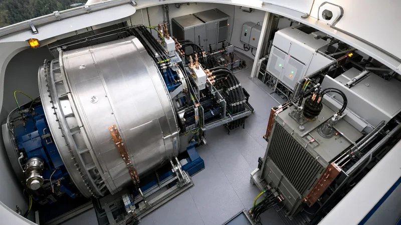
Key takeaways
- Wind turbine electrical components convert low-speed mechanical rotation into synchronised medium-voltage AC power adhering to IEC 61400-21 grid compliance codes.
- Modern multi-megawatt turbines deploy either Doubly Fed Induction Generators (DFIG) with partial-scale converters or Permanent Magnet Synchronous Generators (PMSG) paired with full-scale power converters.
- The step-up transformer elevates generation voltages (typically 690 V to 1.14 kV) to medium-voltage collection levels (typically 33 kV or 34.5 kV) within the tower base or nacelle.
- Mechanical drivetrains transfer rotor torque from the main shaft wind turbine assembly across earthing rings and bearing insulation to prevent electrical pitting caused by shaft voltages.
- Harmonic mitigation and continuous reactive power control are mandatory for modern wind turbines to meet Low-Voltage Ride-Through (LVRT) standards under IEEE 2800 and IEC 61400-1.
Quick answer: The core wind turbine electrical components comprise the generator, four-quadrant power conversion system, step-up transformer, pitch and yaw drive actuators, medium-voltage switchgear, and supervisory control systems. Together, these subsystems convert variable aerodynamic rotor torque into grid-compliant 50 Hz or 60 Hz alternating current at collection voltages up to 36 kV.
Extracting commercial power from variable wind resources requires tightly integrated electromechanical systems capable of continuous thermal and electrical cycling. The electrical drivetrain bridges mechanical rotation and the utility network, managing transient events, high-frequency harmonics, and abrupt voltage fluctuations across tens of thousands of operational hours. For balance-of-plant designers, plant operators, and procurement engineers, selecting and matching each sub-assembly directly dictates plant uptime, Levelised Cost of Energy (LCOE), and regulatory compliance at the point of common coupling.
Do wind turbines rotate and how kinetic energy converts to electricity?
Wind turbines rotate because aerodynamic lift forces exerted across the aerofoil blades generate rotational torque about the rotor hub. When ambient wind velocities exceed the typical cut-in speed of 3 m/s to 4 m/s, the pitching control system orientates the blades to create an asymmetrical pressure differential between the windward and leeward surfaces, initiating rotation.
The mechanical energy path proceeds through several stages before electrical generation occurs:
- Aerodynamic capture: Three pitch-regulated blades absorb kinetic wind energy, operating at rotational speeds typically between 6 rpm and 18 rpm for utility-scale rotors exceeding 100 metres in diameter.
- Torque transfer: The hub transfers high torque at low rotational velocity into the nacelle structure via the primary drivetrain.
- Speed transformation: In geared topologies, a combined planetary-helical gearbox accelerates this low-speed rotation up to 1,200 rpm to 1,800 rpm to feed an induction generator. In direct-drive architectures, this stage is bypassed entirely.
- Electromechanical conversion: The rotor drives magnetic flux linkages inside the generator stator, inducing variable-frequency alternating currents (AC).
- Power conditioning: Active IGBT converters rectify the raw variable-frequency AC to a direct-current (DC) link before reconstructing a fixed-frequency 50 Hz or 60 Hz AC output.
Aerodynamic rotation stops automatically when wind velocities surpass cut-out limits, typically 25 m/s, to safeguard structural integrity using full feathering pitch actuators and high-speed mechanical brakes.
The wind turbine shaft and mechanical-to-electrical drive interface
The wind turbine shaft assembly provides the mechanical conduit that transfers massive low-speed aerodynamic torque from the hub into the generator while isolating electrical subsystems from structural vibration. In utility installations, the main shaft wind turbine component is cast or forged from high-tensile alloy steel such as 34CrNiMo6 or 42CrMo4, dimensioned to resist immense multi-axis bending moments alongside pure torsional forces.
From an electrical engineering standpoint, the main shaft assembly presents significant electrical integrity challenges:
- Shaft voltages and bearing currents: High-frequency pulse-width modulated (PWM) switching from modern inverters induces parasitic capacitive coupling across generator bearings. Without proper mitigation, shaft voltages discharge across lubrication films, leading to fluting, micro-pitting, and early bearing failure.
- Galvanic earthing and grounding rings: Industrial shaft grounding assemblies, featuring copper-graphite or silver-alloy grounding brushes, run directly against the slip rings of the rotating shaft to ground stray currents into the nacelle chassis.
- Lightning current transfer: The main shaft accommodates dedicated spark gaps or heavy-duty slide contacts engineered to route lightning strikes from blade receptors directly into the tower down-conductors, avoiding sensitive power circuits.
Proper alignment between the main shaft, elastic mechanical couplings, and generator rotor maintains the air gap tolerance (often under 2 mm to 4 mm in multi-megawatt machines) required for balanced magnetic flux distributions and consistent voltage generation.
Core wind turbine electrical components: generators, converters, and switchgear
The core sub-assemblies inside the nacelle and tower convert variable mechanical force into medium-voltage electrical power ready for substation transmission. Modern wind turbine electrical components must maintain tight synchronisation with the utility grid despite rapid shifts in incoming wind velocity.
Modern utility architectures deploy two primary generation and conversion schemes:
- Doubly Fed Induction Generators (DFIG): The stator connects directly to the 690 V bus, while the wound rotor links to the grid via a bidirectional back-to-back PWM converter rated at roughly 30% of total turbine capacity. DFIG configurations yield high conversion efficiency at lower capital expense, though rotor slip rings demand regular brush maintenance.
- Permanent Magnet Synchronous Generators (PMSG): Often deployed in direct-drive or medium-speed drivetrains, PMSG designs utilise rare-earth rotor magnets. 100% of the generated electrical power passes through a fully rated power conversion system. This structure provides complete decoupling from grid disturbances, exceptional low-voltage ride-through capability, and zero slip-ring maintenance.
Subordinate to the primary generation path are auxiliary systems: yaw motors and drives that rotate the multi-tonne nacelle into the wind, blade pitch electro-hydraulic or servo-motor systems, and 690 V industrial motor control centres (MCCs). The medium-voltage interface terminates in internal MV switchgear featuring vacuum circuit breakers and three-position disconnector switches, compliant with IEC 62271-200, protecting cabling down the tower drop.
Step-up transformers in wind power generation
Step-up transformers elevate generation-level voltages (typically 690 V, 960 V, or 1.14 kV) to collection-circuit levels (typically 22 kV, 33 kV, or 34.5 kV) to minimise I²R cable losses over the inter-array network. Depending on the nacelle envelope and foundation design, these units are installed either directly inside the nacelle rear, within the tower transition piece, or on an external concrete pad adjacent to the tower base.
Specifying a transformer for wind generation requires unique design considerations compared to standard distribution units, as detailed in our wind turbine transformer engineering guide:
- Severe thermal and mechanical cycling: Turbines experience constant load variations dictated by gusting winds, causing accelerated cyclical expansion and contraction of core and winding assemblies.
- High harmonic spectrums: Inverter switching produces non-sinusoidal currents rich in 5th, 7th, 11th, and higher-order harmonics, demanding transformer designs with elevated K-factors (typically K-4 to K-13) and electrostatic shielding between windings to prevent high-frequency capacitive transfer.
- Environmental footprint: Units located inside the tower base or nacelle commonly specify cast resin dry-type transformers or high-fire-point synthetic/natural ester fluid-filled transformers rated to K-class flammability standards according to IEC 60076-16 to eliminate fire risks in enclosed spaces.
External step-up arrangements frequently rely on robust pad-mounted transformers featuring loop-feed bushings and integrated protective fuse links, balancing accessibility and environmental containment.
Technical comparison: electrical drivetrain configurations
Comparing wind turbine drivetrain and electrical topologies requires evaluating generator parameters, converter sizing, operational harmonics, and maintenance overheads. The choice dictates the specification of all downstream switchgear, protection relays, and step-up transformers.
| Engineering Metric | Geared DFIG Architecture | Direct-Drive PMSG Architecture | Medium-Speed Geared PMSG |
|---|---|---|---|
| Generator Nominal Voltage | 690 V AC (Stator) | 690 V to 1,140 V AC | 690 V to 3,300 V AC |
| Full-Load Rotational Speed | 1,200 to 1,800 rpm | 8 to 15 rpm | 300 to 500 rpm |
| Power Converter Rating | ~30% to 35% of Pn | 100% of Pn | 100% of Pn |
| Step-up Transformer Rating | Pn, low-voltage dual-infeed | Pn, standard primary | Pn, high insulation level |
| Typical Harmonic Distortion (THDi) | Medium (Stator unmitigated) | Low (< 3% at POI) | Low (< 3% at POI) |
| Slip Ring Maintenance Interval | 6 to 12 Months | None (Brushless) | None (Brushless) |
| Standard Compliance | IEC 61400-1 / IEEE 1547 | IEC 61400-1 / IEEE 2800 | IEC 61400-1 / IEEE 2800 |
While DFIG topologies maintain a capital cost advantage due to smaller active converter footprints, full-converter PMSG configurations have become the dominant choice for offshore and remote utility arrays due to superior low-voltage ride-through compliance and reduced maintenance downtime.
Harmonic mitigation and grid integration compliance checklist
Turbine electrical subsystems must satisfy stringent interconnection standards such as IEC 61400-21, IEEE 2800-2022, and regional grid codes at the collector bus. Proper coordination between active filter controls, passive LC filter banks, and step-up transformer impedances mitigates resonance and voltage distortion across the inter-array network.
Commissioning engineers and EPC teams should follow this systematic electrical validation checklist prior to final energisation:
- Insulation resistance and polarisation index: Verify stator, rotor, and transformer winding insulation using a 2.5 kV or 5 kV DC megohmmeter, verifying minimum resistance thresholds according to IEEE 43.
- Shaft earthing ring continuity: Test the impedance of the main shaft wind turbine grounding brushes to the nacelle earth plane, ensuring contact resistance does not exceed 1.0 Ohm.
- Phase alignment and sequence check: Verify positive phase sequence (A-B-C / three-phase rotation) across generator outputs, converter terminals, and step-up transformer bushings prior to closing the main breaker.
- Harmonic distortion verification: Measure Total Demand Distortion (TDD) and individual harmonic magnitudes at nominal load using a Class-A power quality analyser, cross-referencing values with IEEE 519 limits.
- Fault ride-through (FRT) logic simulation: Validate active converter controls to ensure dynamic reactive current injection within 20 milliseconds of a symmetrical or asymmetrical voltage dip as required for modern grid integration of renewable energy sources.
Next steps: specifying and sourcing
When specifying medium-voltage step-up transformers, switchgear, and containerised collector substations for utility-scale wind farms, precise mechanical and electrical data prevents design delays. Prepare your site-specific parameters—including nominal generator output voltage, target inter-array collection voltage (typically 33 kV to 36 kV), short-circuit levels, harmonic spectrum profiles, and environmental classifications (standard environmental, climatic, and fire behaviour classes or ambient extremes from -40°C to +50°C).
Review our factory-engineered prefabricated transformer substations and custom dry-type or ester-filled wind generation transformers engineered to IEC 60076-16 and IEEE C57.12 standards. To submit single-line diagrams (SLDs) or request detailed engineering evaluations, connect with our technical sales engineers through our transformer quotation page or directly via our contact page.
Frequently asked questions
do wind turbines rotate
Yes, wind turbines rotate when aerodynamic lift generated by wind flowing over the curved rotor blades produces torque. The rotation typically starts at a cut-in speed of 3 m/s to 4 m/s and operates between 6 rpm and 18 rpm for utility-scale machines before power conversion occurs.
What are the primary wind turbine electrical components?
The primary electrical components are the electric generator (induction or permanent magnet), back-to-back power electronic converter, step-up transformer, medium-voltage switchgear, yaw and pitch drive actuators, and the supervisory control and data acquisition (SCADA) system.
Why does a wind turbine need a step-up transformer?
Turbine generators produce electricity at low voltages, typically 690 V to 1,140 V. The step-up transformer elevates this voltage to 22 kV, 33 kV, or 34.5 kV, drastically reducing transmission current and minimising thermal line losses across the wind farm collector network.
What is the function of the main shaft in a wind turbine?
The main shaft connects the aerodynamic rotor hub to the mechanical drivetrain or generator. It transfers high mechanical torque while supporting heavy bending moments and houses electrical grounding systems to divert lightning and protect bearings from induced shaft voltages.
What voltage do utility-scale wind turbine generators produce?
Most utility-scale turbines generate electricity at low AC voltages between 690 V and 1,140 V. A small subset of direct-drive offshore turbines utilise medium-voltage generators operating at 3.3 kV or 6.6 kV before feeding the main step-up transformer.
Tags: wind turbine electrical components wind power transformers main shaft wind turbine renewable grid integration wind turbine shaft


