Key takeaways
- Wye (Star) connections split line voltage across two phase windings by a factor of 1.732, reducing inrush current during starting, whereas Delta connections apply full line-to-line potential across each winding for rated continuous torque.
- NEMA dual-voltage induction motors use 9-lead configurations where low-voltage connections place phase windings in parallel and high-voltage connections place them in series.
- IEC 60034-8 standardises terminal designations for winding start and end connections, allowing direct bridge-bar conversion between Star and Delta without re-pulling line conductors.
- Feeder circuit sizing under NEC Article 430.22 requires conductors rated to at least 125% of the motor full-load current (FLC), coordinated with thermal overload and short-circuit protection.
- Reversing the rotational sequence of any three-phase motor requires swapping exactly two incoming line supply phases (L1 and L2) at the motor starter or terminal lugs.
Quick answer: Industrial 3 phase wiring motors diagrams depict the terminal layouts used to connect three-phase AC induction stators to balanced supply lines in either Wye (Star) or Delta configurations. Depending on standard designation (NEMA 9-lead or 12-lead, or IEC 6-lead), windings are bridged in series or parallel to match site operating voltages such as 230/460 V or 400/690 V.
Correctly terminating a polyphase induction motor requires a clear understanding of phase angle relationships, terminal marking conventions, and dual-voltage topology. Whether commissioning low-voltage plant infrastructure fed from 480V 3 phase power networks or designing feeder distribution systems under industrial power system installation guidelines, reading and applying standard 3 phase wiring motors diagrams ensures equipment safety, rated torque output, and compliance with thermal insulation boundaries.
Wye vs Delta Configurations: Fundamental Operating Principles
A three-phase induction motor stator houses three independent phase windings displaced mechanically and electrically by 120 electrical degrees. Connecting these windings in Wye (Star) establishes a common neutral point, meaning the line-to-neutral voltage across each individual winding coil equals the line-to-line supply voltage ($V_{LL}$) divided by the square root of three ($\sqrt{3} \approx 1.732$). Conversely, in a Delta ($\Delta$) configuration, each winding is placed directly between two supply lines, exposing the winding insulation to the full line-to-line voltage.
Because the impedance of the stator winding remains constant, applying the Wye topology reduces line starting current to approximately 33% of the direct-on-line (DOL) Delta starting current, accompanied by an identical reduction in starting torque. This electrical relationship forms the basis for classic Star-Delta reduced-voltage starters. When specifying motor circuits from distribution sources, engineers must verify that the local supply system matches the nameplate winding arrangement. For further details on motor sizing and torque curves, review our three phase electric motor guide.
3 Phase Wiring Motors Diagrams for 6-Lead, 9-Lead, and 12-Lead Stators
Standard 3 phase wiring motors diagrams depend on whether the stator conforms to IEC terminal nomenclature (IEC 60034-8 clause 5) or NEMA conventions (NEMA MG 1 Part 2 Clause 2.62). The internal arrangement dictates whether the motor supports single-voltage operation, dual-voltage series/parallel switching, or part-winding start sequences.
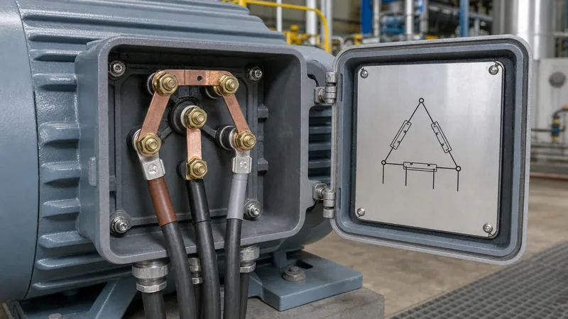
IEC motors standardly supply six terminal studs in the conduit box labeled U1, V1, W1 on one side and W2, U2, V2 directly opposite. For a low-voltage Delta connection, solid copper link bars bridge terminals U1 and W2, V1 and U2, and W1 and V2, with incoming supply phases L1, L2, and L3 terminated on U1, V1, and W1. For high-voltage Star operation, a single link bar connects terminals W2, U2, and V2 to form the internal neutral star point, while line conductors connect to U1, V1, and W1.
NEMA 9-lead motors feature windings numbered T1 through T9. In dual-voltage systems (e.g., 230/460 V):
- Low-Voltage Wye (Parallel Wye, 230 V): L1 connects to T1 and T7; L2 connects to T2 and T8; L3 connects to T3 and T9; leads T4, T5, and T6 are tied together to form an isolated star point.
- High-Voltage Wye (Series Wye, 460 V): L1 connects to T1; L2 connects to T2; L3 connects to T3; leads T4 to T7, T5 to T8, and T6 to T9 are spliced together in three independent pairs.
- Low-Voltage Delta (Parallel Delta, 230 V): L1 connects to T1, T6, and T7; L2 connects to T2, T4, and T8; L3 connects to T3, T5, and T9.
- High-Voltage Delta (Series Delta, 460 V): L1 connects to T1; L2 connects to T2; L3 connects to T3; splices join leads T6 and T9, T4 and T7, and T5 and T8.
Twelve-lead motors bring out both ends of all six internal coils (T1 to T12), permitting dual-voltage operation in both Wye and Delta as well as Star-Delta reduced-voltage starting on the lower voltage tap.
Step-by-Step 3 Ph Motor Wiring and Terminal Termination Procedure
Executing field terminations for 3 ph motor wiring requires strict adherence to isolation protocols and mechanical torque standards to prevent loose, high-resistance joints. Follow this structured commissioning sequence:
- Isolate and Lock Out Power: Verify zero energy state using an appropriately rated, calibrated two-pole voltage detector tested against an active proving unit.
- Perform Insulation Resistance (IR) Testing: Before making physical terminations, measure the stator phase-to-phase and phase-to-ground resistance using a 500 V or 1000 V DC megohmmeter per IEEE 43 Clause 12. A minimum reading of 100 M$\Omega$ at 40°C is standard for modern Class F insulated machines.
- Dress and Identify Conductors: Strip each incoming three phase motor wire using calibrated stripping tools, ensuring no copper strands are nicked. Fit compression lugs (crimp ring terminals) using a calibrated ratchet crimper.
- Position Bridge Links: Arrange internal terminal jump links according to the wiring diagram on the terminal box lid for your target voltage (e.g., parallel vs series).
- Torque Terminal Fasteners: Secure lugs to the threaded studs using stainless steel or brass flat washers, split lock washers, and brass nuts. Torque nuts to specification (typically 4.0 Nm for M5 studs, 6.0 Nm for M6 studs per IEC 60947-1 Table 4).
- Verify Rotation Direction: Bump the contactor momentarily. If mechanical shaft rotation opposes driven equipment requirements, swap incoming supply leads L1 and L2 at the isolation starter.
Cable Sizing and Electric Motor 3 Phase Connection Calculations
Designing an electric motor 3 phase connection requires precise coordination between motor full-load current (FLC), continuous conductor ampacity, and upstream overcurrent protection devices. Under NFPA 70 (NEC) Article 430.22, motor branch-circuit conductors supplying a single continuous-duty motor must possess an ampacity rating not less than 125 percent of the motor rated full-load current.
Consider a 30 kW (40 HP) industrial squirrel-cage induction motor operating at 400 V line-to-line, three-phase, 50 Hz, with a rated full-load efficiency ($\eta$) of 93.6% (IE3 class) and a full-load power factor ($\cos\phi$) of 0.85:
First, calculate the motor Full-Load Current ($I_{FLC}$):
$$I_{FLC} = \frac{P_{out} \times 1000}{\sqrt{3} \times V_{LL} \times \eta \times \cos\phi}$$
$$I_{FLC} = \frac{30{,}000}{1.732 \times 400 \times 0.936 \times 0.85} = \frac{30{,}000}{551.48} \approx 54.4\text{ A}$$
Applying the 125% continuous sizing factor per NEC 430.22:
$$I_{conductor} = 54.4\text{ A} \times 1.25 = 68.0\text{ A}$$
Selecting multi-core XLPE-insulated copper cable run in conduit per IEC 60364-5-52 Table B.52.4 (Installation Method B2) indicates a minimum conductor cross-section of 16 mm² (rated up to 76 A at 30°C ambient). For upstream branch-circuit short-circuit protection using an inverse-time molded case circuit breaker (MCCB) per NEC Table 430.52 (maximum 250% of FLC):
$$I_{breaker} = 54.4\text{ A} \times 2.50 = 136.0\text{ A}$$
Select a standard 125 A or 150 A frame breaker with an adjustable magnetic pickup set above the motor locked-rotor inrush (typically $6 \times I_{FLC} \approx 326\text{ A}$). Matching supply feeders to lower plant voltages, such as commercial building mains, often involves dedicated 208V 3 phase power step-down transformers to handle these starting surges without severe voltage dip.
Three Phase Electric Motor Connections Decision and Troubleshooting Table
Selecting the appropriate configuration among standard three phase electric motor connections depends on grid voltage, mechanical starting duty, and cable conductor counts. The comparative matrix below provides field engineering criteria, common pitfalls, and fault isolation metrics:
| Configuration Type | Terminal Count | Standard Voltage Range | Starting Current Factor | Typical Applications | Primary Failure Mode |
|---|---|---|---|---|---|
| Direct Wye (Star) | 3 or 6 leads | 380 V to 690 V | 1.0 × $I_{FLC}$ (Low) | High-inertia fans, centrifugal pumps | Single phasing under high starting load |
| Direct Delta | 3 or 6 leads | 220 V to 480 V | 5.5 – 7.5 × $I_{FLC}$ | High breakaway loads, conveyors, crushers | Winding insulation puncture via voltage transients |
| Parallel Wye (Low) | 9 leads | 208 V to 240 V | 6.0 – 8.0 × $I_{FLC}$ | North American dual-voltage machine tools | Cross-phase miswiring at star point leads T4, T5, and T6 |
| Series Wye (High) | 9 leads | 440 V to 480 V | 6.0 – 8.0 × $I_{FLC}$ | Industrial plant equipment on 480 V mains | Unbalanced phase current from loose series tap |
| Star-Delta Transition | 6 or 12 leads | 380/660 V or 400/690 V | Starts at 0.33 × Delta, jumps on transition | Compressors, chiller plants, deep well pumps | Transition open-circuit transient arc-over |
When troubleshooting unbalanced running current, measure phase-to-phase voltages directly at the motor conduit box. Voltage imbalance exceeding 1.0% per NEMA MG 1-2016 Clause 14.36 results in winding temperature rises exceeding 25%, drastically degrading winding insulation life.
Next steps: specifying and sourcing
Designing robust motor branch circuits requires matching motor starting currents with resilient upstream distribution equipment. When planning motor control centres or upgrading facility power, explore our engineered HV/LV switchgear and high-efficiency dry-type transformers designed to handle heavy industrial inductive loads and harmonic heating. If your facility requires custom step-down transformers or compact package substations for new motor installations, submit your single-line diagrams, voltage ratios, and starting current profiles through our transformer quotation portal or reach out directly via our engineering contact page for project sizing support.
Frequently asked questions
how to connect a 3 phase motor in star and delta
To connect in Star on an IEC motor, bridge terminals W2, U2, and V2 together with copper links and connect supply lines L1, L2, and L3 to U1, V1, and W1. For Delta, place parallel bridge links between terminals U1 and W2, V1 and U2, and W1 and V2, terminating L1, L2, and L3 on U1, V1, and W1.
how to wire a 9 lead 3 phase motor
For low voltage (230 V Wye), connect L1 to T1 and T7, L2 to T2 and T8, L3 to T3 and T9, and splice T4, T5, and T6 together. For high voltage (460 V Wye), connect L1 to T1, L2 to T2, L3 to T3, and join the series pairs T4 to T7, T5 to T8, and T6 to T9.
how do you reverse the direction of a 3 phase motor
Reverse a three-phase motor by swapping any two of the three incoming supply lines, such as interchanging line L1 and line L2 at the contactor or terminal box. This alters the stator magnetic field's phase rotation sequence, reversing rotor direction.
what is the difference between 6 lead and 9 lead motor wiring
A 6-lead motor exposes both ends of each of the three internal stator phase windings, standard in IEC designs for Delta or Star linking. A 9-lead motor features three internally paired coils typically arranged for dual-voltage operation in North American NEMA systems.
what wire gauge is required for a 3 phase motor
Conductor wire gauge is determined by sizing to at least 125% of the motor full-load current (FLC) per NEC Article 430.22, cross-referenced with insulation temperature ratings and installation method ampacity tables such as NEC Table 310.16 or IEC 60364-5-52.
Tags: 3 phase wiring motors diagrams 3 ph motor wiring three phase motor wire electric motor 3 phase connection three phase electric motor connections


