Key takeaways
- An AC voltage transformer steps alternating voltages up or down via mutual electromagnetic induction at a constant operational frequency.
- Three-phase AC power transformer sizing requires calculating line current using the apparent power formula: I = S / (V × √3).
- Specifying an ac to ac transformer demands explicit compliance with insulation levels, including basic impulse level (BIL) defined under IEC 60076-3 or IEEE C57.12.00.
- Liquid-immersed AC transformers deliver superior dielectric dissipation and thermal performance for outdoor medium-voltage installations compared to dry-type alternatives.
- Short-circuit impedance (%Z) directly governs fault current let-through, busbar mechanical bracing requirements, and downstream switchgear interrupting capacities.
Quick answer: An ac voltage transformer is a static electromagnetic device that transfers alternating current electrical energy between circuits at different voltage levels while maintaining system frequency. Sizing and selecting an industrial unit requires matching continuous kVA rating, primary and secondary system voltages, insulation class, and short-circuit impedance to network fault conditions and load profiles.
In commercial, utility, and heavy industrial distribution networks, alternating current voltage management dictates system stability and equipment longevity. Stepping grid transmission voltages down to operational medium and low voltages involves complex dielectric, thermal, and magnetic considerations. Whether configuring distribution units for manufacturing facilities, infrastructure plants, or renewable substations, selecting the proper transformer topology prevents costly thermal derating, premature insulation breakdown, and catastrophic arc-flash incidents.
How an AC Voltage Transformer Works: Working Principles
An alternating current transformer operates on Faraday's law of mutual electromagnetic induction. When sinusoidal alternating voltage is applied to the primary winding, it establishes a time-varying magnetic flux in the laminated silicon steel or amorphous metal core. This magnetic flux links the secondary winding through the core path, inducing an alternating electromotive force (EMF) proportional to the turn ratio.
According to Faraday's law, the induced voltage in any winding is expressed by the fundamental equation:
E = 4.44 × f × N × Φmax
Where f is the system frequency in hertz (typically 50 Hz or 60 Hz), N represents the number of winding turns, and Φmax represents the peak magnetic flux in webers (defined as the core cross-sectional area multiplied by the operational peak flux density, typically 1.6 to 1.7 Tesla for grain-oriented electrical steel). In an ideal transformer, the voltage ratio equals the winding turn ratio: Vp / Vs = Np / Ns = Is / Ip. Understanding these magnetic boundaries ensures the core operates safely below magnetic saturation, preventing elevated excitation currents and harmonic distortion under overvoltage conditions per IEC 60076-1 clause 5.4.
Types of AC to AC Transformer Units in Power Distribution
Industrial facilities implement various transformer configurations depending on environmental conditions, installation siting, and structural fire separation requirements. Selecting between fluid-filled and dry-type insulation platforms is the primary structural decision during electrical project front-end engineering design (FEED).
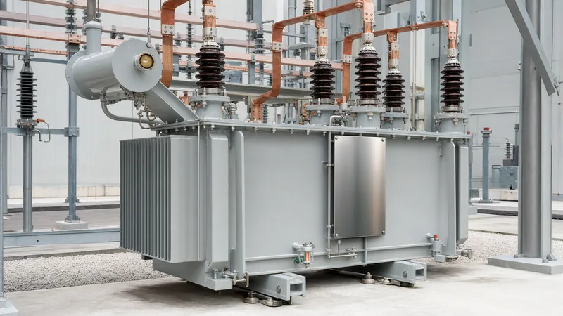
For outdoor distribution substations and industrial service entrances, an oil-immersed transformer provides high dielectric strength, exceptional basic impulse level (BIL) withstand, and efficient heat rejection. For indoor environments, high-density commercial complexes, and underground utility vaults where fire safety is paramount, a cast resin or vacuum pressure impregnated dry-type transformer eliminates liquid containment sumps and passive fire deluge requirements. Engineers reviewing radial versus network topologies can consult our detailed analysis on radial feed vs loop feed systems to ensure layout reliability.
Technical Comparison: Oil-Immersed vs Cast Resin Dry-Type
Evaluating insulation systems requires balancing capital expenditure, operational losses, environmental exposure, and footprint constraints. The following comparison highlights key engineering parameters governed by IEC 60076 and IEEE C57.12 standards.
| Engineering Parameter | Oil-Immersed Distribution (ONAN) | Cast Resin Dry-Type (AN) | Evaluation Standard |
|---|---|---|---|
| Dielectric Fluid / Medium | Mineral Oil / Synthetic Ester | Epoxy Resin / Solid Dielectric | IEC 60296 / IEC 60076-11 |
| Winding Temperature Rise Limit | 65 K (over 40°C ambient) | 100 K to 125 K (Class F/H) | IEC 60076-2 / IEEE C57.12.01 |
| BIL Rating (at 24 kV Class) | 125 kV to 145 kV peak | 95 kV to 125 kV peak | IEC 60076-3 Table 2 |
| Fire Risk Classification | O1 / K2 (Synthetic Ester) | F1 (Self-extinguishing) | IEC 60076-11 clause 20 |
| Environmental Protection | IP54 to IP65 (Hermetic tank) | IP00 to IP33 (Enclosure dependent) | IEC 60529 |
| Short-Circuit Mechanical Withstand | High (dynamic fluid dampening) | Rigid (encapsulated winding) | IEC 60076-5 |
| Overload Capacity (Short Duration) | High thermal time constant (3-4 hrs) | Lower thermal time constant (1-2 hrs) | IEC 60076-7 |
To examine standard kVA tiers across international voltage classes, refer to our comprehensive guide on standard transformer sizes.
Step-by-Step Electrical Sizing and Full-Load Current Calculation
Accurate sizing of an ac to ac transformer requires evaluating both continuous apparent power demands and the corresponding full-load ampacity across primary and secondary terminal connections. Undersizing leads to excessive winding temperature rises and accelerated thermal degradation of paper or resin insulation under IEEE C57.91 thermal aging rules.
- Determine Total Connected Load (kVA): Sum the operational loads, applying appropriate continuous duty diversity and coincidence factors across distinct equipment groupings.
- Factor Load Growth and Power Factor: Incorporate anticipated facility expansion (typically 20% to 25%) and divide active real power (kW) by the operational power factor (cos φ, typically 0.85 to 0.90) to establish total apparent demand: SkVA = PkW / cos φ.
- Calculate Three-Phase Rated Full-Load Current: Use the three-phase current formula: Irated = (SkVA × 1000) / (Vline × √3).
- Verify Short-Circuit Impedance (%Z): Confirm the transformer impedance percentage satisfies fault interrupting ratings of downstream switchgear while maintaining acceptable motor starting voltage drop (typically ≤ 10% during large motor start-up).
For a detailed breakdown of mathematical formulas across single-phase and multi-phase connections, review our resource on transformer current calculation formulas. Furthermore, engineers sizing complex unbalanced systems should utilize our tutorial on how to determine kVA for precise electrical matching.
Worked Engineering Example: Sizing a 1000 kVA Substation Transformer
Consider an industrial manufacturing facility requiring a dedicated transformer ac step-down unit connected to an 11 kV medium-voltage distribution ring, feeding a 415 V three-phase motor control center (MCC).
1. Input Parameters:
- Connected real power demand: 680 kW
- Operational operating load power factor: 0.82 lagging
- Specified future load growth allowance: 20%
- Primary supply voltage (line-to-line): 11,000 V (11 kV)
- Secondary operating voltage (line-to-line): 415 V (0.415 kV)
- System frequency: 50 Hz
- Primary connection / Secondary connection: Delta / Wye-grounded (Dyn11)
2. Apparent Power Requirement Calculation:
Baseline continuous apparent power: Sbase = 680 kW / 0.82 = 829.27 kVA
Accounting for 20% future load expansion margin: Sdesign = 829.27 × 1.20 = 995.12 kVA
Selecting the nearest standard IEC distribution kVA rating yields a standard unit size of 1000 kVA.
3. Full-Load Current Verification:
Primary Full-Load Current (11 kV):
Iprimary = (1000 × 1000) / (11,000 × 1.73205) = 1,000,000 / 19,052.56 = 52.49 A
Secondary Full-Load Current (415 V):
Isecondary = (1000 × 1000) / (415 × 1.73205) = 1,000,000 / 718.80 = 1,391.21 A
4. Short-Circuit Let-Through Evaluation:
Assuming a standard guaranteed short-circuit impedance of Z% = 5.0% per IEC 60076-5 Table 1, the symmetrical symmetrical fault level available at the secondary LV terminals (ignoring source utility impedance for conservative worst-case estimation) is:
Isc(LV) = Isecondary / (Z% / 100) = 1,391.21 A / 0.05 = 27,824 A = 27.82 kA
Consequently, secondary low-voltage switchboards and circuit breakers must feature a minimum short-circuit breaking capacity (Icu) of 36 kA or 50 kA to clear secondary fault conditions safely.
Critical Factory Testing and Specification Checklist
When preparing an inquiry or review documentation for an ac voltage transformer, consulting engineers must mandate compliance with rigorous factory acceptance testing (FAT) regimes. Missing test definitions can result in unverified losses, elevated sound power levels, and undetected core defects prior to site delivery.
Incorporate the following mandatory criteria directly into your equipment technical specification schedule:
- Routine Dielectric Testing: Separate source AC withstand voltage test and short-duration induced AC overvoltage test (IVW) per IEC 60076-3 clause 11 to prove insulation clearance and turn-to-turn integrity.
- Loss Measurement and Guarantees: No-load core losses (iron losses) and full-load winding losses (copper losses corrected to 75°C or 120°C reference temperature) verified under IEC 60076-1 clause 11.5 with strictly capped tolerance margins (typically +15% on individual losses, +10% on total losses).
- Winding Resistance & Vector Verification: High-precision Kelvin bridge resistance measurement on all tap positions, combined with angular vector phase displacement check (e.g., Dyn11, Ynd11).
- Sound Level Certification: Sound pressure and sound power measurements taken in an acoustic chamber according to IEC 60076-10 to satisfy municipal and industrial noise boundaries.
- Partial Discharge Verification: Crucial for cast resin and dry-type units, ensuring partial discharge levels remain below 10 pC at 1.30 × Um/root(3) line-to-earth test levels under IEC 60076-11.
Next steps: specifying and sourcing
Specifying the optimal transformer requires validating site ambient conditions, altitude derating factors, short-circuit levels, and target efficiency thresholds. To advance your project procurement, assemble your site load data, single-line diagrams (SLD), and environmental constraints before requesting manufacturing proposals. Explore our heavy-duty power transformer solutions for high-voltage substations, or examine our fully engineered modular transformer substation enclosures for turnkey power delivery. To submit your engineering schedules or request a detailed factory quotation for custom-built distribution units, visit our direct quote page or submit technical schedules through the contact page.
Frequently asked questions
What is the primary function of an ac voltage transformer?
An AC voltage transformer transfers alternating electrical energy between circuits while changing voltage levels through mutual electromagnetic induction. It steps voltages up for transmission efficiency or down for industrial distribution without modifying the operational system frequency.
Can an AC voltage transformer operate on a direct current (DC) supply?
No, an AC voltage transformer cannot operate on steady-state DC power. Transformer operation relies strictly on alternating magnetic flux to induce voltage in the secondary winding; steady DC produces constant flux, causing near-zero induced voltage and destructive primary overcurrent.
What is the difference between an instrument voltage transformer and a power voltage transformer?
An instrument voltage transformer (VT/PT) steps down high voltages with high ratio accuracy solely to feed protective relays, metering, and control devices with negligible VA burden. A power voltage transformer is designed to transfer bulk power continuously to operational electrical loads.
How does ambient temperature and altitude affect AC transformer sizing?
Operating an AC transformer at ambient temperatures above 40°C or altitudes exceeding 1000 metres reduces dielectric cooling air density and fluid heat rejection. According to IEC 60076-2, continuous kVA ratings must be derated by approximately 0.4% per 100 metres above standard altitude.
Why is short-circuit impedance (%Z) critical when selecting an AC transformer?
Short-circuit impedance dictates internal voltage drop under full load and governs the magnitude of available prospective fault current during a secondary short circuit. Higher %Z lowers secondary short-circuit current stresses but produces higher operational voltage regulation drops.
Tags: ac voltage transformer transformer ac ac to ac transformer transformer sizing electrical engineering


