Key takeaways
- Transformers are rated by their capacity in apparent power (kVA or MVA) rather than active power (kW) because internal thermal limits depend on current and voltage regardless of load power factor.
- IEC 60076-1 establishes preferred standard transformer sizes based on the Renard R10 series (e.g., 100, 160, 250, 400, 630, 1000 kVA).
- IEEE C57.12.00 and NEMA define North American three-phase steps including 75, 112.5, 150, 225, 300, 500, 750, 1000, 1500, 2000, and 2500 kVA.
- Selecting the nearest standard transformer size above peak demand avoids custom factory re-tooling costs, long manufacturing lead times, and spare part sourcing delays.
- Specifying non-standard kVA ratings can increase purchase price by 15% to 30% without delivering operational or efficiency advantages.
Quick answer: Standard transformer sizes are standardised apparent power ratings—measured in kilovolt-amperes (kVA) or megavolt-amperes (MVA)—defined by international standards bodies such as IEC and IEEE/NEMA. Common three-phase distribution sizes include 100, 160, 250, 400, 630, 1000, 1600, and 2500 kVA under IEC rules, and 75, 112.5, 150, 225, 300, 500, 750, 1000, 1500, 2000, and 2500 kVA under North American IEEE conventions.
Procuring power distribution equipment requires strict alignment with established manufacturing increments. When electrical engineers calculate site demand, peak loads rarely land precisely on an exact commercial size. Knowing the standard transformer sizes specified in utility regulations and global standards ensures optimal transformer life, minimizes capital expenditure, and avoids the lengthy lead times associated with custom-engineered magnetic cores. Selecting an off-the-shelf rating also simplifies future replacements and network expansion across industrial, commercial, and utility installations.
Why Transformers Are Rated by Their Capacity in kVA and MVA
Transformers are rated according to apparent power rather than real power because copper losses depend purely on current while iron core losses depend on operating voltage. The total heating within the magnetic core and winding conductors limits the operating threshold of any transformer, irrespective of the phase displacement between current and voltage caused by inductive or capacitive loads.
In alternating current (AC) power systems, transformers are rated by their capacity in kilovolt-amperes (kVA) for distribution equipment and megavolt-amperes (MVA) for substation units. Real power, measured in kilowatts (kW), depends entirely on the downstream power factor (cos φ) of the connected load, as expressed in the basic relationship:
kVA = kW / cos φ
If a 1000 kVA transformer supplies a purely resistive heating load with a unity power factor (1.0), it can safely deliver 1000 kW without exceeding its temperature rise class. However, if that same transformer supplies industrial induction motors operating at a lagging power factor of 0.80, the maximum real power output is restricted to 800 kW. Supplying 1000 kW at 0.80 power factor would demand 1250 kVA, causing severe thermal overload, dielectric degradation of the winding insulation, and premature asset failure. For detailed mathematical conversions between current draw, phase configurations, and load ratings, refer to our kVA to amperes calculation guide.
Standard Transformer Sizes: IEC vs IEEE Preferred Ratings
Standard transformer sizes differ between international markets primarily due to the distinct standardization paths of the International Electrotechnical Commission (IEC) and the Institute of Electrical and Electronics Engineers (IEEE) alongside NEMA.
IEC 60076-1 clause 5.4 adopts preferred numbers based on the Renard R10 series, which provides logarithmic step increases of roughly 60% between consecutive steps (multiplier of 10^(1/10) ≈ 1.25 or 10^(1/5) ≈ 1.58). Conversely, North American practices governed by IEEE C57.12.00 Table 5 evolved around conventional imperial engineering increments. Sizing three-phase oil-immersed transformers or dry-type transformers requires clear identification of which standard dictates site specifications.
| Standard Series | Single-Phase Ratings (kVA) | Three-Phase Distribution Ratings (kVA) | Substation & Power Ratings (MVA) |
|---|---|---|---|
| IEC 60076-1 (R10 Series) | 16, 25, 40, 63, 100, 160, 250 | 50, 100, 160, 250, 400, 630, 800, 1000, 1250, 1600, 2000, 2500, 3150 | 4.0, 5.0, 6.3, 8.0, 10.0, 12.5, 16.0, 20.0, 25.0, 31.5, 40.0, 50.0 |
| IEEE C57.12.00 / NEMA | 10, 15, 25, 37.5, 50, 75, 100, 167, 250, 333, 500 | 15, 30, 45, 75, 112.5, 150, 225, 300, 500, 750, 1000, 1500, 2000, 2500, 3750 | 3.75, 5.0, 7.5, 10.0, 12.0, 15.0, 20.0, 25.0, 30.0, 37.5, 50.0, 75.0 |
Attempting to order an intermediate capacity, such as an IEC 550 kVA or an IEEE 600 kVA unit, requires non-standard core laminations, bespoke winding mandrels, and custom tank fabrication. These non-standard requests can elevate upfront capital costs by 20% to 35% while creating substantial lead times when field replacements are required.
Typical Transformer Sizes for Single-Phase and Three-Phase Systems
Typical transformer sizes vary systematically according to mounting configuration, network phase count, and the physical environment of the installation site.
Single-phase distribution units frequently serve rural electrification, overhead residential networks, and light trackside railway equipment. In North America and parts of Latin America, single-phase pole-mounted transformers commonly utilize 15, 25, 37.5, 50, and 75 kVA ratings. These single units step medium-voltage utility feeds (such as 13.8 kV or 24.94 kV) down to split-phase 120/240 V consumer supply. For an in-depth breakdown of single-phase core constructions and applications, see our single phase transformer guide.
Three-phase distribution networks dominate industrial plants, commercial buildings, and urban commercial zones. The most frequent commercial sizes deployed inside industrial substations are 500, 750, 1000, 1500, 2000, and 2500 kVA. Pad-mounted installations serving commercial shopping centres and institutional campuses lean heavily on standardized 300, 500, 1000, and 1500 kVA liquid-filled configurations. For integrated installations combining primary isolation switches, transformers, and secondary low-voltage switchboards into one enclosure, engineers reference unit substation engineering guidelines to match footprint constraints to the required kVA base.
Utility Transformer Sizes and Power Transformer Ratings
Utility transformer sizes scale significantly above distribution classes, stepping up into primary sub-transmission and bulk transmission voltages from 33 kV up to 400 kV and higher.
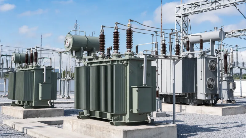
A power transformer rating in a utility substation is typically governed by active cooling stages. Standards define multi-stage ratings based on whether cooling relies entirely on natural convection or is assisted by mechanical equipment:
- ONAN (Oil Natural Air Natural): The continuous base self-cooled rating without fans or external pumps operating.
- ONAF (Oil Natural Air Forced): The enhanced thermal capacity achieved by activating automated auxiliary radiator fans, typically increasing base capacity by 25% to 33%.
- OFAF / ODAF (Oil Forced Air Forced / Oil Directed Air Forced): Maximum forced-circulation rating utilizing high-volume oil pumps and blowers, providing up to a 66% capacity uplift over the base ONAN value.
Consequently, high-voltage utility power transformers routinely carry triple-split nameplate ratings, such as 15/20/25 MVA or 30/40/50 MVA. Substation planners design normal seasonal baseloads around the ONAN rating, preserving the ONAF and OFAF thresholds for peak demand intervals or N-1 emergency contingency conditions when adjacent network equipment trips offline.
Worked Sizing Calculation: Selecting a Standard kVA Rating
Selecting a standard transformer rating requires converting total connected electrical load into real expected demand and applying contingency safety margins.
To size a transformer correctly for an industrial manufacturing facility, follow this sequential procedure:
- Tabulate all connected loads categorized by duty (lighting, HVAC, electric motors, auxiliary loads).
- Apply appropriate demand factors and diversity factors to determine concurrent peak operational kW.
- Divide the continuous peak kW by the operational power factor to establish base apparent power in kVA.
- Apply future plant expansion margins (typically 20% to 25%).
- Select the next higher standard transformer size from the applicable IEC or IEEE catalogue.
Worked Example:
Consider a proposed industrial plant with the following verified electrical criteria:
- Total connected continuous load: 720 kW
- Plant operating power factor: 0.84 lagging
- Anticipated load growth over a 10-year horizon: 20%
- Design ambient temperature limit: 40 °C (IEC 60076 reference condition)
Step 1: Calculate the unexpanded base apparent load requirement:S_base = 720 kW / 0.84 = 857.14 kVA
Step 2: Add the required 20% long-term facility growth allowance:S_design = 857.14 kVA × 1.20 = 1028.57 kVA
Step 3: Map the result to standardized ratings.
Under IEC 60076-1, the available standard transformer sizes surrounding this figure are 1000 kVA and 1250 kVA. Selecting the 1000 kVA unit would leave the transformer operating at 102.8% of capacity under full future load, which accelerates insulation thermal ageing according to Arrhenius rate laws. Therefore, the correct selection is 1250 kVA. For rapid cross-checking of varied plant profiles, engineers can utilize our transformer calculator sizing guide.
Specification Checklist for Standard Transformer Procurements
A comprehensive engineering specification prevents project delays by ensuring all standard mechanical and electrical parameters match plant switchgear interfaces.
When compiling a Request for Quotation (RFQ) for standard transformer units, verify the following factory parameters:
- Primary and Secondary Voltage Ratings: Explicitly state no-load rated voltages (e.g., 11,000 V to 415 V, or 13,800 V to 480Y/277 V) and whether secondary neutral brings full current-carrying capacity.
- Standard kVA Capacity: Specify base cooling class (ONAN/AN) and any secondary forced-air stage ratings (ONAF/AF).
- Vector Group and Phase Displacement: Confirm primary-secondary winding connections (e.g., Dyn11, Dyn1, or YNd11) to maintain synchronisation with adjacent site substations.
- Percent Impedance (%Z): State standard factory impedance (typically 4.0% to 5.0% for units ≤ 630 kVA; 5.75% to 6.25% for 1000 kVA to 2500 kVA per IEC 60076-5) to govern fault currents and switchgear short-circuit breaking duties.
- Off-Circuit Tap Changer (OCTC) or On-Load Tap Changer (OLTC): Standard taps typically span ±2 × 2.5% or ±5% to adjust for utility primary voltage drop.
- Temperature Rise Limits: Specify maximum winding and top-oil rises (e.g., 65 °C / 60 °C for liquid-immersed mineral oil; 100 °C / 125 °C rise for Class H dry-type units).
Next steps: specifying and sourcing
Selecting the optimal standard transformer sizes balances operational efficiency, initial capital expenditure, and spare-unit interchangeability across your facility network. To proceed with your procurement or finalize design schematics, prepare your single-line diagram, target medium-voltage grid parameter sheets, design fault level restrictions, and ambient site environment conditions. Explore our heavy-duty pad-mounted transformers and specialized distribution units engineered to international standards. When you are ready to review detailed equipment drawings, loss guarantees, or routine test certificates, submit your technical parameters directly through our transformer quotation portal.
Frequently asked questions
What are the most common standard transformer sizes for commercial buildings?
The most common three-phase distribution transformer sizes for commercial buildings are 500 kVA, 750 kVA, 1000 kVA, 1500 kVA, and 2000 kVA. In North American installations, 112.5 kVA, 150 kVA, and 300 kVA are also standard for smaller commercial structures.
Why are transformers rated in kVA instead of kW?
Transformers are rated in kVA because their electrical and thermal limits depend strictly on voltage and current, which cause core losses and copper heating. The actual power in kW delivered by the unit depends on the downstream power factor of the connected load.
What happens if you undersize a distribution transformer?
Undersizing a transformer forces windings to operate above their design thermal classification, accelerating insulation degradation and reducing operational lifespan. It can also produce excessive voltage drops at terminal lugs and cause thermal protection relays to trip under peak loads.
What is the difference between IEC and IEEE standard transformer sizes?
IEC transformer sizes follow the Renard R10 geometric progression, yielding common distribution increments like 100, 160, 250, 400, 630, and 1000 kVA. IEEE/NEMA transformer sizes follow North American commercial increments such as 75, 112.5, 150, 225, 300, 500, 750, and 1000 kVA.
Can you operate a standard transformer above its rated kVA?
Yes, oil-filled transformers can operate above their continuous ONAN kVA rating by activating auxiliary cooling fans (ONAF) or through short-term emergency overloading permitted by IEC 60076-7 or IEEE C57.91, provided ambient thermal limits are monitored.
Tags: standard transformer sizes typical transformer sizes transformer ratings power transformer rating utility transformer sizes


