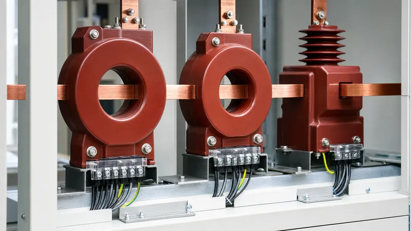
Key takeaways
- A current transformer ratio expresses the relationship between rated primary current and rated secondary current, standardising secondary outputs to either 1 A or 5 A.
- Selecting an optimal current transformer ratio requires sizing the primary rating between 100% and 125% of the circuit full-load continuous current under normal operations.
- Protection current transformers must avoid magnetic core saturation during maximum asymmetrical through-faults by maintaining adequate secondary knee-point voltage per IEC 61869-2.
- Multi-ratio current transformer taps provide field-selectable secondary ratios on a single physical core, but secondary winding resistance rises proportionally at lower tap settings.
- Secondary circuits of energised current transformers must never be left open-circuited because lethal peak voltages will develop across the terminals due to core flux saturation.
Quick answer: A current transformer ratio (CTR) is the mathematical relationship between the rated primary alternating current and the standardised secondary alternating current, typically expressed as a fraction such as 400:5 A or 1200:1 A. It scales hazardous transmission or distribution currents down to measurable, safe values for protective relays, digital meters, and monitoring instruments.
In electrical power distribution and substation design, selecting the correct instrument transformer parameters prevents metering errors, protective relay misoperation, and catastrophic equipment damage. When designing networks incorporating switchgear, power transformers, and circuit breakers, specifying the proper instrument transformer involves balancing continuous thermal ratings, core saturation limits, secondary burdens, and fault-clearing dynamics. Correct specification ensures that secondary protection elements detect phase-to-phase and ground faults accurately without saturating during severe through-fault conditions.
Current Transformer Ratio Fundamentals and Standards
A current transformer operates on the principle of magnetic induction, matching primary ampere-turns to secondary ampere-turns according to the classic transformer equation where primary current multiplied by primary turns equals secondary current multiplied by secondary turns ($I_p \times N_p = I_s \times N_s$). In standard window or bushing configurations, the primary winding consists of a single pass through the magnetic core ($N_p = 1$), meaning the secondary turns directly govern the transformation ratio.
International standards govern how these ratios are defined and tested. Under IEC 61869-2 (which superseded IEC 60044-1), rated secondary currents are strictly standardised to 1 A or 5 A, with 1 A predominantly chosen for installations with long secondary cable runs to minimise the $I^2R$ burden losses. North American practice, governed by IEEE C57.13, also recognises 5 A secondary ratings as standard for switchgear and control house relaying. Understanding how these transformers interact with main equipment is critical during system design, particularly when commissioning assets detailed in our power transformer testing guide or executing substation testing procedures.
Understanding Current Transformer Ratings and Accuracy Classes
Standard current transformer ratings define the continuous thermal current rating factor (RF), rated insulation level, rated frequency, and accuracy class under specified burden constraints. The thermal rating factor specifies the multiple of rated primary current that the transformer can carry continuously at a designated ambient temperature (typically 30°C or 55°C) without exceeding the insulation thermal class limits defined in IEC 60085.
Instrument transformers are segregated into two distinct operational classes: metering cores and protection cores.
- Metering Class: Designed to provide extreme accuracy between 5% and 120% of rated continuous current. These cores are engineered to saturate intentionally at moderate overcurrents (typically 1.2 to 2 times rated current) using low-saturation steels to protect delicate connected meters from high fault currents. Common IEC accuracy classes include 0.2S and 0.5S, denoting a maximum ratio error of 0.2% and 0.5% over the specified current range.
- Protection Class: Designed to maintain magnetic linearity up to extreme fault current levels. Under IEC 61869-2, a 5P20 protection core specifies a composite error under 5% at 20 times the rated primary current when connected to its rated burden. IEEE C57.13 defines protection performance by relay accuracy designations such as C400 or C800, where 'C' denotes that the ratio correction factor can be calculated (non-subdivided window type) and the number designates the secondary terminal voltage the transformer can deliver at 20 times rated secondary current without exceeding 10% ratio error.
Current Transformer Sizing Chart and Selection Parameters
Selecting the correct primary current rating requires matching the nominal load current while verifying that short-circuit current levels do not saturate the core. Sizing the primary rating at 110% to 125% of the circuit full-load continuous current ensures that standard load variations do not drive meters into inaccurate measurement zones.
The following current transformer sizing chart outlines typical primary to secondary ratios, secondary burden limits, and minimum knee-point voltage requirements across typical medium-voltage (MV) feeder and transformer applications:
| Circuit Voltage (kV) | Continuous Load (A) | Standard CT Ratio | Burden Rating (VA / $\Omega$) | Recommended Core Class | Typical Application |
|---|---|---|---|---|---|
| 0.415 kV | 160 A | 200:5 A | 5 VA (0.2 $\Omega$) | Class 0.5 Metering | LV Switchboard Billing |
| 11 kV | 280 A | 300:5 A | 15 VA (0.6 $\Omega$) | 5P10 Protection | Distribution Feeder O/C |
| 11 kV | 520 A | 600:1 A | 10 VA (10 $\Omega$) | 5P20 Protection | Transformer Incomer Protection |
| 33 kV | 185 A | 200:1 A | 15 VA (15 $\Omega$) | Class X / PX | Unit Transformer Differential |
| 33 kV | 750 A | 1000:1 A | 30 VA (30 $\Omega$) | 0.2S Metering | Grid Interconnection Boundary |
When selecting ratios for switchgear, engineers should consult ratings implemented in medium-voltage switchgear engineering to verify compatibility between busbar thermal ratings and transformer core mounting windows.
Worked Calculation: Current Transformer Ratio and Burden Verification
A worked engineering calculation demonstrates how to determine whether a chosen ratio and burden rating will saturate during a maximum external through-fault. Consider an 11 kV feeder supplied by a 10 MVA transformer with an impedance of 8.0%. The downstream maximum symmetrical three-phase fault current ($I_{fault}$) is calculated as:
$$I_{fault} = \frac{S_{base}}{\sqrt{3} \times V_{line} \times Z_{pu}} = \frac{10\text{ MVA}}{\sqrt{3} \times 11\text{ kV} \times 0.08} = 6560.8\text{ A}$$
The circuit full-load continuous current is approximately 525 A. We select a standard current transformer ratio of 600:5 A (transformation ratio $N = 120$). The secondary fault current ($I_{sec, fault}$) reaching the relay is:
$$I_{sec, fault} = \frac{6560.8\text{ A}}{120} = 54.67\text{ A}$$
Next, we sum the total connected secondary burden impedance ($Z_{total}$), comprising the internal secondary winding resistance ($R_{ct}$), the secondary lead wire resistance ($R_{lead}$), and the relay input impedance ($R_{relay}$):
- Internal winding resistance ($R_{ct}$): $0.15\ \Omega$
- Secondary leads (50 metres of 4.0 mm² copper wire, round trip of 100 m at $0.00461\ \Omega/\text{m}$): $0.461\ \Omega$
- Relay input burden ($R_{relay}$): $0.05\ \Omega$
- Total secondary burden ($Z_{total}$): $0.15 + 0.461 + 0.05 = 0.661\ \Omega$
The secondary saturation voltage requirement ($V_{req}$) during symmetrical fault conditions equals the secondary fault current multiplied by the total loop burden:
$$V_{req} = I_{sec, fault} \times Z_{total} = 54.67\text{ A} \times 0.661\ \Omega = 36.14\text{ V}$$
To account for direct-current (DC) offset components during an asymmetrical fault, an operational DC offset multiplier ($X/R$ factor) must be applied. Assuming an electrical system $X/R$ ratio of 10, the required excitation knee-point voltage ($V_k$) under IEC 61869-2 clause 5.6 to avoid transient saturation during primary fault inception is:
$$V_k \ge V_{req} \times \left(1 + \frac{X}{R}\right) = 36.14\text{ V} \times (1 + 10) = 397.54\text{ V}$$
Therefore, a protection core rated at C400 or possessing an IEC knee-point voltage greater than 400 V is required to prevent relay misoperation. For specialized protection schemes, such as those covered in our transformer protection guide, failing to compute the DC saturation factor leads directly to nuisance differential relay tripping.
Configuring Multi-Ratio Cores and Current Transformer Taps
Multi-ratio instrument transformers utilise tapped secondary windings that allow engineers to alter the transformation ratio without physically replacing the device. These current transformer taps provide system flexibility when substation load projections predict steady growth over decades, enabling an initial lower ratio that can be stepped up as plant demand expands.
A typical multi-ratio transformer compliant with IEEE C57.13 features five external secondary terminals designated X1, X2, X3, X4, and X5, producing ten available ratio combinations from a single core. The table below illustrates the standard tap configuration for a 1200:5 A multi-ratio current transformer:
| Terminal Tap Connection | Available Ratio | Secondary Turns ($N_s$) | Internal Resistance ($R_{ct}$ in $\Omega$) | Relay Voltage Class |
|---|---|---|---|---|
| X2 - X3 | 100:5 A | 20 | 0.052 | C50 |
| X1 - X2 | 200:5 A | 40 | 0.104 | C100 |
| X1 - X3 | 300:5 A | 60 | 0.156 | C150 |
| X4 - X5 | 400:5 A | 80 | 0.208 | C200 |
| X3 - X5 | 500:5 A | 100 | 0.260 | C250 |
| X2 - X4 | 600:5 A | 120 | 0.312 | C300 |
| X1 - X4 | 800:5 A | 160 | 0.416 | C400 |
| X3 - X4 | 900:5 A | 180 | 0.468 | C450 |
| X2 - X5 | 1000:5 A | 200 | 0.520 | C500 |
| X1 - X5 (Full Winding) | 1200:5 A | 240 | 0.624 | C600 |
A critical operational consideration when selecting intermediate taps is the dramatic reduction in effective terminal voltage capability. When operating on the 300:5 A tap (intermediate tap terminals), only one-quarter of the physical turns are active, dropping the knee-point voltage to approximately 25% of the full-winding C600 capability ($150\text{ V}$). Protection engineers must evaluate through-fault saturation specifically at the assigned tap rather than relying on the nameplate rating of the full secondary winding.
Field Testing and Commissioning Current Transformer Ratio Settings
Commissioning verification prevents wiring errors, polarity inversions, and incorrect tap configurations prior to energisation. Testing procedures should strictly follow standards outlined in IEEE C57.13.1 and IEC 61869-2 clause 7.
- Secondary Winding Resistance Measurement: Measure DC resistance across all connected taps using a low-resistance digital ohmmeter. Record values and correct to 75°C reference temperature.
- Polarity Verification: Apply a pulsed DC voltage (using a low-voltage battery source) to the primary winding (primary terminals) while monitoring secondary deflection on an analogue voltmeter across the active secondary terminals. An upward deflection confirms proper subtractive polarity.
- Turns Ratio and Phase Displacement Test: Apply an alternating test voltage below the saturation point to the secondary winding and measure the induced primary voltage with a precision digital voltmeter. The ratio of secondary applied voltage to primary induced voltage must match the calculated turns ratio within $\pm 0.5\%$ for metering cores and $\pm 1.0\%$ for protection cores.
- Excitation Curve and Knee-Point Test: Inject an AC test voltage incrementally onto the secondary terminals while monitoring excitation current until a 10% increase in voltage yields a 50% increase in magnetising current. This point marks the knee-point voltage according to IEC definitions.
- Secondary Burden Verification: Measure the total loop impedance of the secondary wiring and connected protection relays with an AC impedance meter to ensure total installed burden does not exceed the core nameplate VA rating.
Safety Precautions and Open-Circuit Hazards
The secondary winding of an energised current transformer must never be disconnected or allowed to operate in an open-circuit state. Because a current transformer acts as a constant current source driven by the primary load, opening the secondary circuit reduces the opposing demagnetising secondary ampere-turns to zero.
With no secondary demagnetising field, the entire primary current acts as magnetising current, forcing the magnetic core into deep saturation. The rapid flux collapse during every alternating current zero induces extremely high peak voltages across the secondary terminals, frequently reaching several thousand volts ($3\text{ kV} - 10\text{ kV}$). These lethal voltage spikes will flash over terminal blocks, puncture internal secondary insulation, generate extreme core overheating through eddy current losses, and present a fatal shock hazard to operating personnel. Always install shorting terminal blocks and confirm the insertion of shorting pins prior to disconnecting any secondary instrument loop.
Next steps: specifying and sourcing
When specifying current transformers for utility, commercial, or industrial applications, preparing a complete electrical schedule ensures accurate pricing and manufacturing lead times. Provide our engineering team with your system single-line diagrams, nominal and maximum primary current values, short-circuit withstand levels ($I_{cw}$ and duration), physical mounting configurations (bushing, window, or bar-primary), required accuracy classes, and burden requirements.
We integrate high-precision instrument transformers directly into our complete equipment lines, including power transformers, custom HV and LV switchgear, and outdoor transformer substations. For comprehensive technical consultation, detailed quotation documentation, and factory test planning, visit our quote request page or contact our electrical engineering department directly.
Frequently asked questions
What is current transformer ratio?
A current transformer ratio is the proportion of rated primary current to rated secondary current, such as 400:5 A or 1000:1 A. It determines how many amperes in the primary conductor produce one ampere in the secondary monitoring circuit.
How to calculate current transformer ratio?
Calculate the current transformer ratio by dividing the circuit full-load continuous current by the desired secondary input rating (1 A or 5 A), then rounding up to the nearest standard primary current rating. For example, a 380 A load on a 5 A relay system requires a 400:5 A ratio.
What happens if a current transformer secondary is left open?
Leaving an energised current transformer secondary open causes the entire primary current to magnetise the core, resulting in severe magnetic saturation. This produces lethal peak voltages of several thousand volts across the terminals, destroying internal insulation and creating an electrocution hazard.
Why choose a 1A secondary over a 5A secondary current transformer?
A 1 A secondary is selected when long cable distances separate the transformer from the relay panel. Because secondary burden loss scales with the square of the current ($I^2R$), a 1 A circuit generates only 4% of the cable resistance voltage drop produced by a 5 A circuit.
What does a current transformer accuracy class 5P20 mean?
A 5P20 accuracy class denotes an IEC protection current transformer that maintains composite error within 5% at 20 times its rated primary current. This ensures protective relays receive undistorted current measurements during heavy fault conditions without core saturation.
How do multi-ratio current transformer taps work?
Multi-ratio current transformer taps provide intermediate connection points along the secondary winding. Selecting different terminal combinations varies the active turns ratio, enabling adjustable primary-to-secondary scaling on a single physical core to accommodate future load expansion.
Tags: current transformer ratio current transformer sizing chart current transformer ratings current transformer taps


