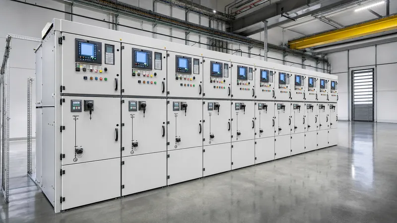
Key takeaways
- Medium-voltage switchgear controls, protects, and isolates electrical equipment operating between 1 kV and 52 kV according to IEC 62271-200 and IEEE C37.20.2 standards.
- Metal-clad switchgear provides full physical segregation between the busbar, circuit breaker, cable, and low-voltage compartments with metallic partitions to prevent fault propagation.
- Loss of Service Continuity (LSC) classification determines network availability during maintenance, with LSC2B-PM providing the highest level of isolation for critical continuous-process plants.
- Rated short-circuit breaking capacity must be calculated using prospective substation fault levels, including DC component decay and peak making current multipliers of 2.5 or 2.6.
- Internal Arc Classification (IAC AFLR) verifies that personnel surrounding the MV panel are protected against hot gas expulsion and fragments during an internal arc event of up to 1 second duration.
Quick answer: MV switchgear (medium-voltage switchgear) is an integrated assembly of electrical switching, interrupting, and measuring devices operating between 1 kV and 52 kV that isolates faults, reconfigures distribution networks, and protects critical equipment such as transformers, motors, and feeders.
In electrical distribution systems, medium-voltage assemblies serve as the primary junction point between high-voltage transmission substations and low-voltage end-use facilities. Whether deployed in heavy manufacturing, data centres, utility substations, or large renewable energy parks, the performance of an mv switchgear line-up dictates overall plant reliability and operational safety. A failure at this node can cause cascading plant outages, catastrophic equipment damage, and severe personnel hazards through arc flash incidents.
Specifying and procuring medium-voltage apparatus requires a precise understanding of international engineering standards, arc-resistant structural classifications, duty cycles, and circuit breaker physics. Modern facilities often coordinate these medium-voltage assemblies directly with HV and LV switchgear and downstream power step-down systems to maintain absolute power continuity.
What Is MV Switchgear and How Does It Operate?
An mv switchgear assembly comprises factory-assembled, grounded metal enclosures that house primary switching devices, continuous copper or aluminium busbars, instrument transformers, protective relays, and auxiliary control apparatus operating from 1 kV up to 52 kV under IEC terminology, or 1 kV up to 38 kV under IEEE standards.
The fundamental operating principle is the controlled isolation and clearing of both normal load currents and abnormal short-circuit fault currents. When an overcurrent or earth fault occurs on a downstream feeder, instrument transformers detect the elevated current and step it down to standard secondary values (typically 1 A or 5 A). The microprocessor-based numerical protection relay analyses this signal against programmed time-current characteristic curves. Upon exceeding the trip threshold, the relay energises the trip coil of the circuit breaker within 20 to 50 milliseconds. The primary contacts separate inside a specialised quenching medium—predominantly vacuum or sulphur hexafluoride (SF6)—extinguishing the electrical arc at current zero and isolating the faulted circuit before thermal and mechanical stresses destroy upstream infrastructure.
For facilities managing upstream connections from bulk distribution networks, our companion analysis on the electrical switchgear system architecture details the progression from high-voltage intake to secondary distribution.
Metal-Clad vs Medium Voltage Metal Enclosed Switchgear
The mechanical and structural construction of medium-voltage enclosures dictates their reliability, safety, and physical segregation during maintenance.
Standard engineering frameworks differentiate sharply between medium voltage metal enclosed switchgear and metal-clad switchgear. Under IEEE C37.20.2, metal-clad switchgear represents the most stringent construction classification. It requires that all major primary components—namely the primary switching device, the main busbars, incoming and outgoing cable terminations, and instrument transformers—be housed in completely segregated, grounded metal compartments. Metallic barriers prevent an electrical fault in one compartment from migrating to adjacent sections. Furthermore, circuit breakers in metal-clad gear must be fully withdrawable (rackable), incorporating automatic shutters that mechanically cover primary busbar stabs when the breaker is racked out to the disconnected or test position.
Conversely, medium voltage metal enclosed switchgear conforming to IEEE C37.20.3 houses switches, fuses, and busbars within a common grounded metallic enclosure, but without mandatory continuous metal partitions between individual internal components. These assemblies frequently utilise fixed-mounted devices, making them more compact and cost-effective for non-critical loads, auxiliary services, or installations where downtime for manual isolation is acceptable.
Under international standards (IEC 62271-200 clause 3.1.104), this operational distinction is formally defined through Loss of Service Continuity (LSC) categories:
- LSC1: Opening any compartment requires de-energising the entire switchgear assembly. Commonly found in simple, single-enclosure substations.
- LSC2A: Opening a functional compartment (such as the cable termination chamber) permits the main busbar to remain energised, but adjacent functional units in the same section may be affected.
- LSC2B: Maximum continuity. When the circuit breaker compartment of a functional unit is opened, both the high-voltage cable compartment and the main busbars remain fully energised and operational.
- Partition Class PM: Segregation between compartments is achieved entirely by metallic partitions and shutters, which are bonded to the protective earth circuit.
- Partition Class PI: Segregation is achieved using non-metallic, insulating partitions.
For applications where space is constrained and switching points are limited, engineers often evaluate how metal-clad units compare with sealed ring systems, as explored in our guide on ring main units vs metal-clad switchgear.
Medium Voltage Switchgear Specification: Sizing and Calculations
A comprehensive medium voltage switchgear specification must define both continuous steady-state parameters and transient withstand ratings in accordance with IEC 62271-1 or IEEE C37.04.
Key rating parameters include:
- Rated Voltage ($U_r$): The maximum upper operating voltage (RMS value) of the system (e.g., 3.6 kV, 7.2 kV, 12 kV, 17.5 kV, 24 kV, or 36/40.5 kV). In North American industrial settings, 5kv switchgear (rated at 4.76 kV nominal maximum) is a standard design point for 4.16 kV distribution systems.
- Rated Insulation Level: Defined by power-frequency withstand voltage (e.g., 28 kV RMS for 1 minute at 12 kV) and lightning impulse withstand voltage (BIL), such as 75 kV or 95 kV crest.
- Rated Continuous Current ($I_r$): The maximum RMS current that main busbars and runbacks carry continuously without exceeding temperature rise limits (typically 630 A, 1250 A, 2000 A, 2500 A, 3150 A, or 4000 A per IEC 62271-1 Table 14 limits).
- Rated Short-Time Withstand Current ($I_k$): The thermal RMS current the assembly carries in the closed position during a short circuit for a rated duration, standardly 1 s or 3 s (e.g., 25 kA, 31.5 kA, 40 kA, 50 kA).
- Rated Peak Withstand Current ($I_p$): The instantaneous peak current that mechanical bracing must withstand against electromagnetic repulsion forces during the first cycle.
Consider an industrial manufacturing facility fed by a 20 MVA, 33 kV to 11 kV step-down transformer having an impedance of $Z\% = 8.0\%$, connected to an infinite 33 kV utility grid. An engineer must size the incoming 11 kV mv panel.
1. Calculate the full-load rated current ($I_{FLC}$) on the 11 kV secondary:
$$I_{FLC} = \frac{S_{rated}}{\sqrt{3} \times V_{LL}} = \frac{20{,}000\text{ kVA}}{\sqrt{3} \times 11\text{ kV}} = \frac{20{,}000}{19.052} \approx 1050\text{ A}$$
2. Calculate the prospective symmetrical short-circuit current ($I_{sc}$) on the 11 kV busbar:
$$I_{sc} = \frac{I_{FLC}}{Z_{pu}} = \frac{1050\text{ A}}{0.08} = 13{,}125\text{ A} = 13.125\text{ kA}$$
3. Calculate the required breaking capacity with a safety margin. In real-world installations, motor contributions from large induction motors on the medium-voltage bus add roughly 4 to 5 times their rated current to the total fault current. Assuming an aggregate 4 MVA motor load operating at 11 kV ($I_{motor} \approx 210\text{ A}$):
$$I_{sc,motor} = 4.5 \times 210\text{ A} = 945\text{ A} \approx 0.95\text{ kA}$$
$$I_{sc,total} = 13.125\text{ kA} + 0.95\text{ kA} = 14.075\text{ kA}$$
4. Determine the Peak Withstand Current ($I_p$). Per IEC 62271-100 clause 5.101, for systems with a standard time constant of 45 ms at 50 Hz, the peak-to-RMS factor is 2.5 (or 2.6 for 60 Hz per IEEE C37.010):
$$I_p = 2.5 \times I_{sc,total} = 2.5 \times 14.075\text{ kA} = 35.19\text{ kA peak}$$
Consequently, the engineer must specify an 11 kV or 12 kV switchgear assembly with a standard rated short-time breaking current of at least 25 kA for 3 s and a peak withstand of 63 kA peak, providing ample thermal and mechanical margin for future plant expansion.
Circuit Interruption Technologies: Vacuum vs SF6 in an MV Switch
The choice of interruption medium inside the primary mv switch or circuit breaker directly impacts switching endurance, environmental footprint, and dielectric stability.
Vacuum circuit breakers (VCBs) dominate indoor installations from 3.3 kV up to 40.5 kV. In a vacuum interrupter, fixed and moving contacts reside within a high-vacuum ceramic envelope (internal pressure below $10^{-7}\text{ mbar}$). When contacts part under fault conditions, current vaporises contact material, producing a metal-vapour arc. Because diffusion and condensation rates in a vacuum are rapid, the dielectric strength recovers across the gap within microseconds of current zero. Contact materials such as copper-chromium (CuCr) provide high electrical endurance, low contact erosion, and minimal chop current, limiting dangerous switching overvoltages on inductive transformer loads.
Sulphur hexafluoride (SF6) gas-insulated circuit breakers rely on the electronegative properties of SF6 gas to capture free electrons and quench the thermal arc. While SF6 has superior dielectric recovery at higher system voltages (72.5 kV and above) and operates effectively in extremely contaminated or aggressive ambient environments, its global warming potential (GWP of 24,300 relative to CO2) has triggered stringent regulatory phasedowns under European F-Gas regulations and worldwide environmental accords. For standard metal-clad indoor switchgear, vacuum interruption paired with air insulation (AIS) or modern non-SF6 gas alternatives represents the preferred engineering approach.
| Engineering Criteria | Vacuum Circuit Breaker (VCB) | SF6 Circuit Breaker (GCB) |
|---|---|---|
| Interruption Medium | Vacuum (<10⁻⁷ mbar) | SF6 Gas (typical 0.3 - 0.6 MPa) |
| Number of Full-Fault Clearings | 30 to 100 operations | 10 to 30 operations |
| Mechanical Endurance (IEC 62271-100) | Class M2 (10,000 operations) | Class M1 or M2 (2,000 - 10,000 operations) |
| Switching Overvoltages | Moderate (mitigated by CuCr contacts) | Very Low (soft arc quenching) |
| Environmental & Regulatory Status | Zero GWP, non-toxic, unrestricted | High GWP (24,300), strict tracking/taxes |
| Maintenance Demands | Sealed bottle, virtually maintenance-free | Gas density monitoring, leakage refilling |
Medium Voltage Switches, Disconnectors, and Earthing Switches
In addition to heavy-duty circuit breakers, an MV switchgear assembly integrates several types of medium voltage switches engineered for operational switching, visible isolation, and personnel safety.
Each device fulfils a specific role in line management:
- Load Break Switch (LBS): A switching device capable of making, carrying, and breaking currents under normal operating conditions, as well as specified operational overload conditions. An LBS can also close onto a short circuit (making capacity), but it cannot interrupt a fault current. When paired with high-rupturing-capacity (HRC) current-limiting fuses, it provides an economical protection solution for distribution transformers up to 2000 kVA.
- Disconnector (Isolator): Designed per IEC 62271-102 to provide an open, visible isolating distance in the de-energised state. A disconnector has no interrupting capability and can only open or close circuits when negligible current is broken, or when no significant voltage difference occurs across its terminals.
- Earthing Switch: A mechanical device that grounds isolated conductors to dissipate residual electrostatic and electromagnetic charges before personnel access the cable compartment or busbar. Fast earthing switches feature a spring-charged mechanism providing rated short-circuit making capacity (making onto an accidentally live bus without exploding).
Operational safety hinges upon robust mechanical and electrical interlocking. Under IEC 62271-200 clause 6.106, interlocks must mechanically prevent: racking a circuit breaker into the service position when it is closed; closing a breaker unless it is completely in the service or test position; closing an earthing switch while the circuit breaker or disconnector is closed; and opening the cable compartment access door unless the associated earthing switch is fully closed.
Internal Arc Classification (IAC) and Safety Design
Internal arc classification (IAC) certifies that an mv panel enclosure can contain the mechanical pressure wave, thermal energy, and toxic gases produced by an internal arcing fault without endangering operators.
When an internal short circuit occurs, the arc temperature can exceed 15,000 K within milliseconds. Air rapidly expands, vaporising metallic copper and aluminium, which generates massive internal overpressures exceeding 100 to 200 kPa. IEC 62271-200 Annex A defines rigorous type tests to qualify an assembly for an IAC rating. The rating is designated by accessibility, location, current magnitude, and duration—for example, IAC AFLR 31.5 kA 1 s.
The constituent designations represent:
- A: Accessibility restricted to authorised electrical personnel only (industrial/substation access).
- F: Verification of operator safety at the Front of the enclosure.
- L: Verification of operator safety at the Lateral (sides) of the enclosure.
- R: Verification of operator safety at the Rear of the enclosure.
- Current and Duration: The maximum fault current the enclosure contained for the specified period (e.g., 31.5 kA for 1.0 second) without burning through exterior walls or blowing open doors.
To pass the IAC criteria, five baseline test requirements must be fulfilled during the explosive event: correctly secured doors and covers must not open; no enclosure fragmentation exceeding 60 grams occurs; the arc does not burn holes through exterior accessible covers; vertical indicators (cotton fabric cloths mounted 300 mm away from the panel) must not ignite; and the enclosure must remain securely connected to its earthing circuit.
Engineers designing high-risk substations should review the broader mechanics of flashover prevention in our dedicated article on what causes an arc flash and containment principles.
LV MV Electrical Switchgear Integration in Substation Architectures
Integrating lv mv electrical switchgear requires seamless protective coordination, clear physical segregation, and matched secondary measurement circuits across the complete distribution train.
In a standard industrial or commercial primary substation, the medium-voltage gear takes power from a utility source or on-site generator at 11 kV, 22 kV, or 33 kV, and routes it through vacuum circuit breakers to step-down distribution transformers. These transformers lower the voltage to 400 V, 480 V, or 690 V, feeding downstream low-voltage switchboards. Protecting this interface requires precise time-current grading between the MV microprocessor protection relays (such as ANSI 50/51 phase overcurrent and ANSI 50N/51N earth-fault relays) and the low-voltage Air Circuit Breaker (ACB) trip units.
A critical challenge during integration is ensuring that the medium-voltage breaker does not trip prematurely on transformer magnetising inrush current. Inrush typically exhibits peak currents 8 to 12 times the transformer full-load current, decaying over several hundred milliseconds. Protective relays must employ second-harmonic restraint algorithms (blocking trips if second-harmonic content exceeds roughly 15-20%) or intentional short-time grading margins of at least 200 to 300 ms above downstream ACB trip curves. For further details on transformer protection topologies, refer to our guide on substation transformer protection schemes.
Physical packaging is equally critical. For integrated turnkey installations, consulting engineers increasingly specify prefabricated compact substations, which incorporate the MV intake switchgear, cast-resin or liquid-filled distribution transformer, and LV power distribution panel in a factory-tested enclosure.
Procurement and Factory Acceptance Testing: Specification Checklist
Evaluating medium voltage switchgear manufacturers requires auditing both their quality assurance systems and their compliance with mandatory type tests and routine production tests.
Before signing an EPC procurement contract or approving manufacturing drawings, technical teams must conduct a thorough Factory Acceptance Test (FAT) on the fully assembled switchgear train. In accordance with IEC 62271-200 clause 7 and IEC 62271-1, routine factory testing is non-negotiable and encompasses:
- Dielectric Withstand Test on the Main Circuit: Applying power-frequency test voltage (e.g., 28 kV RMS for 12 kV switchgear, 50 kV RMS for 24 kV switchgear) for 60 seconds across open contacts and phase-to-phase / phase-to-earth with contacts closed.
- Dielectric Test on Auxiliary and Control Circuits: Verifying wiring insulation by applying 2 kV RMS for 1 minute to all low-voltage wiring looms and terminal blocks.
- Measurement of Main Circuit Resistance: Measuring contact resistance across primary joints and breaker poles using a DC micro-ohmmeter (typically 100 A DC minimum) to verify that joint resistances match type-tested values (often <40 micro-ohms per pole).
- Mechanical and Interlock Operation Verification: Performing a minimum of 5 to 10 racking cycles of circuit breakers, opening/closing operations of disconnectors and earth switches, and verifying all mechanical and solenoid-driven interlocks.
- Partial Discharge (PD) Screening: Conducting routine PD measurements on vacuum interrupters, busbar supports, and instrument transformers to confirm baseline PD levels remain below 10 pC at 1.1 times maximum rated phase-to-earth operating voltage.
Use the following technical checklist when assembling your tender documentation for medium voltage switchgear suppliers:
| Engineering Parameter | Standard Specification Options | Project-Specific Value |
|---|---|---|
| Applicable Standards | IEC 62271-200 / IEEE C37.20.2 | Specify governing standard |
| Service Condition & Location | Indoor / Outdoor (Kiosk / Shelter) | Specify ambient temp (-25°C to +40°C) & humidity |
| Rated Voltage / Operating Voltage | 7.2 kV / 12 kV / 24 kV / 36 kV | Specify grid nominal & max operating kV |
| Rated BIL (Impulse Withstand) | 60 kV / 75 kV / 95 kV / 125 kV / 170 kV | Match regional transmission/distribution code |
| Rated Continuous Current | 630 A / 1250 A / 2000 A / 3150 A | Main busbar rating & individual feeder ratings |
| Short-Time Withstand (3 s) | 16 kA / 25 kA / 31.5 kA / 40 kA / 50 kA | Based on utility prospective fault level |
| Loss of Service Continuity | LSC2B-PM / LSC2A-PI | LSC2B-PM strongly recommended for process plants |
| Internal Arc Classification (IAC) | IAC AFLR 25 kA 1 s / 31.5 kA 1 s | Specify required accessibility (AFL or AFLR) |
| Circuit Breaker Mechanism | Motor-wound spring-charged stored energy | DC control voltage (24 V, 48 V, 110 V, or 220 V DC) |
| Instrument Transformers | Ring-core or block-type cast resin (0.2S / 5P20) | Specify burden (VA) and accuracy class for CT/VT |
Next steps: specifying and sourcing
When preparing to engage with mv switchgear manufacturers for your upcoming infrastructure, mining, or utility project, early preparation of detailed engineering inputs prevents schedule delays and cost revisions. Ensure your tender package includes a fully defined single-line diagram (SLD), prospective short-circuit fault levels, protection philosophy specifications, control voltage requirements, and site ambient conditions. For tailored engineering guidance, exploring our range of factory-assembled HV/LV switchgear solutions or requesting a comprehensive proposal through our project quotation page connects you directly with our senior electrical application engineering team.
Frequently asked questions
What is the difference between MV switchgear and an RMU?
An MV switchgear line-up is modular and withdrawable, using compartmentalised air-insulated metal-clad panels designed for primary distribution with ratings up to 4000 A and 50 kA. A Ring Main Unit (RMU) is a compact, factory-sealed gas or solid-insulated unit with fixed-mounted switches designed primarily for secondary ring distribution systems up to 630 A.
What is the standard voltage range for medium voltage switchgear?
Under IEC standards, medium voltage switchgear covers assemblies operating between 1 kV and 52 kV AC. Under IEEE/ANSI standards, medium voltage ranges from 1 kV up to 38 kV AC, with standard North American distribution classes operating at 4.76 kV, 15 kV, 27 kV, and 38 kV.
Why is vacuum interruption preferred over SF6 in indoor MV panels?
Vacuum interruption provides a high mechanical endurance of over 10,000 operations, zero risk of toxic gas leakage, and zero greenhouse gas emissions. SF6 has a global warming potential of 24,300, leading to severe international regulatory restrictions, handling costs, and phaseout mandates.
What does an IAC AFLR rating mean on an MV switchgear panel?
An IAC AFLR rating certifies that the switchgear has passed type tests containing an internal explosive arc fault without causing structural failure. The designation verifies protection for personnel positioned at the Front (F), Lateral sides (L), and Rear (R) of the enclosure in authorised (A) industrial operating areas.
How often does an MV circuit breaker require routine maintenance?
Modern vacuum circuit breakers require visual inspection and lubrication every 3 to 5 years or after 2,000 to 5,000 mechanical operations. Full electrical testing—including contact resistance, insulation resistance, and vacuum bottle integrity testing—should occur every 5 to 6 years unless continuous condition monitoring systems are fitted.
What is the difference between LSC2A and LSC2B switchgear?
LSC2B switchgear maintains service to both the main busbar and the incoming power cable compartments when the circuit breaker compartment is opened. In LSC2A switchgear, opening a functional compartment allows the busbar to stay live, but cables connecting to that functional unit must be de-energised.
Tags: mv switchgear mv panel 5kv switchgear medium voltage switchgear specification medium voltage switchgear manufacturers


